TIP141 si a npn silicon power darling tons designed for complementary use with TIP145, TIP146 and TP147. Can stand up to 125 W at 25°C Case Temperature, 10 A Continuous Collector Current and has a minimum hFE of 1000 at 4 V, 5 A. This home audio amplifier can output 30W with a +- 32V symmetric power supply. If you want a stereo power amplifier please check out the other schematics.


| R1=1Kohm | R16-17=270ohm | D1=9.1V 0.4W zener |
| R2=47Kohm | R18=22ohm 1W | D2-3=1N4148 |
| R3=1.5Kohm | R19=NC | Q1-2=BC550C |
| R4-5=10Kohm | R20-21=0.39ohm 4W | Q3=MPSA56 |
| R6=5.6Kohm | TR1=250ohm trimmer | Q4=BC547B |
| R7=10ohm | C1=470nF 100V MKT | Q5=BC212 |
| R8=47Kohm | C2=1nF 100V MKT | Q6=BC183 |
| R9=560ohm | C3=68pF ceramic | Q7-8=MPSAO6 |
| R10-11=8.2Kohm | C4-8=22nF 100V MKT | Q9=TIP141 |
| R12-15=120ohm | C5-6-7=100nF 100V MKT | Q10=TIP146 |
| R13=680ohm | C9=47uF 25V | F1-2=1.6AT FUSE |
| R14=330ohm | C10-11=220uF 63V | All the resistors is 1/4W 1% except quote differently |
30W power amplifier circuit diagram

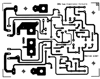
30 Watt audio amplifier PCB


0 comments:
Post a Comment