Showing posts with label booster. Show all posts

Wednesday, November 12, 2014

Rangkaian Booster TV Sederhana

Rangkaian Booster TVThis is circuit that can be used to strengthen the RF signals from a television antenna work at UHF frequencies in the range 450-800MHz. It has a gain of around 10dB and is suitable for boosting weak TV signals
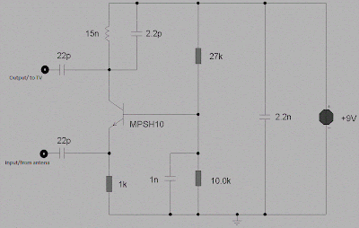
rangkaianSkema rangkaian booster TV sederhana

The tuned circuit comprising the 15nH inductor and 2.2pF capacitor resonate in the center of the UHF band. The 2.2pF capacitor may be Exchanged for a 4.7pF or a Trimmer capacitor of 2-6pF to improve results. The approximate frequency response is shown below. N.B. This is a simulated response using the TINA program produced by using a swept input 20uV swept over the frequency range 400-800MHz. Output was measured into a 1k source and the frequency generator has a 75ohm impedance.

The coil is half a turn of 18-20 SWG copper wire bent around a half inch drill bit. This ensures a low Q and therefore broad tuning. High frequency work requires special construction techniques to avoid instability (unwanted oscillations) caused by feedback from output to input. Veroboard is not suitable for this project as the capacitance between tracks is around 0.2pF. A better approach is to use tag-strip or a PCB. The circuitry should be enclosed in a metal case and a screen made between input and output. As the transistor is used in common base mode, its low input impedance is a good match for 50-75 ohm coax cable, whilst at the same time providing full voltage gain to the upper frequency limit of the device. The 15nH inductor load, having almost a short circuit impedance at DC, has an impedance of 56ohms at 600MHz. This inductance and 2.2pF capacitor form a tank circuit at the transistors collector, providing maximum gain at resonance.

Wednesday, October 29, 2014

MP3 Player Booster Circuits

MP3 players are all the rage these days. The smaller ones in memory-stick format are particularly easy to take with you; your very own ‘personal sound system’ on the move! It’s when you want others to share your taste in music that you find these players to have a lack of power. You can get round this problem with the help of the MP3 booster, a small amplifier that can be used to connect your MP3 player directly to your Hi-Fi. When you next invite your friends to a party you can ask them to bring their ‘personal music’ as well as the usual drinks!

But first we have to build this booster! The small battery-powered players have an output signal that is more than sufficient to drive a set of 32 Ohm headphones. You’ll often find that with an output of 1mW the sound pressure level (SPL) produced can reach up to 90 dB. This would be sufficient to cause permanent damage to your hearing after only one hour! The maximum output voltage will then be around 200mV. This, however, is insufficient to fully drive a power amplifier. For this you’ll need an extra circuit that boosts the output voltage.

Power amps usually require 1 V for maximum output, hence the signal has to be amplified by a factor of five. We will also have to bear in mind that quieter recordings may need to be amplified even more. We’ve used a simple method here to select the gain, which avoids the use of potentiometers. After all, the MP3 player already has its own volume control. We decided to have two gain settings on the booster, one of three times and the other ten times. Amplifiers IC1A and IC1B (for the right and left channels) are housed in a single package, a TS922IN.

The output signal of the MP3 player is fed via a stereo cable and socket K1 to the inputs of the amplifiers. The gain depends on the relationship between resistors R2 and R1 (R6 and R5 for the other channel) and is equal to ten times. When you add jumper JP1 (JP2), resistor R3 (R7) will be connected in parallel with the negative feedback resistor R1 (R6), which causes the gain to be reduced to about three. When you start using the booster you can decide which gain setting works best for you.

Circuit diagram:


MP3 Booster Circuit Diagram

Resistor R4 (R8) takes the amplified MP3 signal to the output socket K2 (K3). A cable then connects these phono sockets to the input of your power amplifier. The resistors connected in series with the output (R4 and R8) are there to keep the booster stable when a long cable is connected to its output. Cables have an unwelcome, parasitic capacitance. This capacitive effect could (due to phase shifts of the signal) affect the negative feedback of the booster in such a way that a positive feed back occurs, with the result that the booster oscillates and possibly damages the power amplifier!

The resistors (R4 and R8) effectively isolate the output of the booster from the parasitic capacitance of the output cable. They also protect the booster outputs from short circuits. We’ve used a TS922IN opamp in this booster because it can operate at very low supply voltages (the maximum is only 12 V!), but can still output a reasonable current (80 mA max.). For the supply we’ve used rechargeable batteries (e.g. NiCd or NiMH cells) so that we don’t need a mains supply.

To keep the number of cells required as small as possible, we’ve chosen a supply voltage of 5 volt; this can be supplied by four rechargeable batteries. It is also possible to use four ordinary, non-rechargeable batteries; it’s true that the supply voltage then becomes a bit higher (6 Volts), but that won’t cause any harm. Since we’ve used a symmetrical supply for the booster (2 x 2 batteries), it will be easiest if you use two separate battery holders, each with two AA cells. The two holders are connected in series.

Make sure that the batteries are connected the right way round; the positive of one always has to be connected to the negative of the next. This also applies to the connection between the two battery holders. S1A/B is a double pole switch, which is used to turn both halves of the battery supply on or off simultaneously. If you can’t find the (dual) opamp we’ve used (or an equivalent), you could always use standard opamps such as the NE5532, TL082 or TL072. These do need a higher supply voltage to operate properly. In these cases you should use two 9 V batteries and replace resistor R9 with a 15 kΩ one.

Do take care when you connect the circuit to your power amplifier because the output signal can be a lot larger and you could overload the power amplifier. (Although you’re more likely to damage the loudspeakers, rather than the amplifier!) (Please note that these two 9 V batteries can’t be used as a supply for the TS922IN!) In our circuit we’ve used a stereo jack socket for the input and phono sockets for the output because these are the most compatible with MP3 players and power amplifiers respectively. If you wanted to, you could solder shielded cables directly to the circuit instead, with the correct plugs on the ends. You’ll never find yourself without the correct connection leads in that case!
Source: Elektor Electronics 12-2006

Wednesday, September 24, 2014

Hydrophone Booster Amplifier HA2

Hydrophone Booster Amplifier (HA2)
The HP series Hydrophone Booster Amplifier (HA2) amplifies low-level hydrophone signals over a wide range of frequencies. It has a minimum gain of 25dB and an input and output impedance of 50Ω. The HA2 is designed for use with either Precision Acoustics membrane hydrophone or Precision Acoustics HP Series Hydrophone Measurement System, which is shown in Fig 1.
Hydrophone Booster Amplifier
Alternatively, the HA2 may be used when the acoustic signal is provided by a high output impedance hydrophone, such as a GEC-Marconi membrane device, or a conventional hydrophone. In this instance a BNC/MCX adaptor is used which connects directly to the HP Series Submersible Preamplifier, using it as a buffer amplifier, (i.e. the standard Precision Acoustic HP Series configuration shown in Fig 1 is used, but without the interchangeable probe).
The HA2 amplifier is straightforward to use but the following points should be noted:
  • The output of the amplifier should be correctly terminated in 50Ω before operation.
  • The HA2 amplifier is non-inverting but this is of no consequence when used with the HP Series interchangeable probes as their design takes this into account. However when a submersible preamplifier is used as a high impedance buffer amplifier (as in Fig 2) the system output from the HA2 will be inverted as the HP Series Submersible Preamplifier is inverting.
Before Connecting the unit please read WARNING
To Connect
To  Disconnect
1 Connect Output Load 1 Remove RF Input
2 Apply DC Voltage 2 Remove DC Volts
3 Apply RF Input 3 Remove Load

Spec (HA2 Amplifier Only)
Voltage Gain = 25dB minimum
Bandwidth =  50kHz to 125MHz ±1.0dB
Maximum Output Level = 29dBm for 1dB compression (18.1V pk – pk into 50Ω load)
Input Impedance = Nominal 50Ω
Output Impedance  Nominal 50Ω (VSWR 2:1)
Output Noise Level = Typically 70μV pk – pk (bandwidth 125MHz)
Noise Figure = Typically 10dB
Phase = Non-inverting
Terminations:
Front panel = Input BNC socket BNC Output socket
Rear panel Power Requirements = 28v dc output to supply DC Coupler 100/120/220/240V ac, 50 to 60Hz,
7.5W
Operating Temperature = 0 to 50°C
Size = (90mm × 205mm ×194mm)
Weight = 2.6kg

Copyright : Precision Acoustics March 2004

USB Power Booster

The USB serial bus can be configured for connecting several peripheral devices to a single PC. It is more complex than RS232, but faster and simpler for PC expansion.Since a PC can supply only a limited power to the external devices connected through its USB port, when too many devices are connected simultaneously, there is a possibility of power shortage. Therefore an external power source has to be added to power the external devices.

Circuit diagram:
USB Power Booster Circuit-Diagram
USB Power Booster Circuit Diagram

In USB, two different types of connectors are used: type A and type  B. The circuit presented here is an add-on unit, designed to add more power to a USB supply line (type-A). When power signal from the PC (+5V) is received through socket A, LED1 glows, opto-diac IC1 conducts and TRIAC1 is triggered, resulting in availability of mains supply from the primary of transformer X1. Now transformer X1 delivers 12V at its secondary, which is rectified by a bridge rectifier comprising diodes D1 through D4 and filtered by capacitor C2.
 Pin configurations of moc302Pin configurations of moc3021, bt136 and 5v regulator 7805

Regulator 7805 is used to stabilise the rectified DC. Capacitor C3 at the output of the regulator bypasses the ripples present in the rectified DC output. LED1 indicates the status of the USB power booster circuit. Assemble the circuit on a general-purpose PCB and enclose in a suitable cabinet. Bring out the +5V, ground and data points in the type-A socket. Connect the data cables as assigned in the circuit and the USB power booster is ready to function.


Author :T.A. BABU  - Copyright:  EFYMAG