Thursday, November 20, 2014

65W Power Amplifier Circuits with HEXFET

65W65W Power Amplifier Circuits with HEXFET

A average ability amplifier that is characterized by a lot of acceptable complete quality, but accompanying is actual simple in the construction. Him uses, abundant time in my alive loudspeakers. In his achievement date abide the actual acceptable FET transistors, technology HEXFET, transistor which are controlled by voltage and no by accepted as the classically bipolar transistors. The ambit has balanced designing, absolute appropriately the harmonic baloney problem.

All the transistors that are acclimated in the ambit are simple and they abide in big clearings in the market. The pairs of cogwheel amplifiers Q1-2 and Q3-4 should be akin amid them and abreast the one in the other. Appropriately you can buy abundant transistors of types BC550C and BC560C, and with a multimeter you bout amid them creating pairs with aforementioned characteristics, ensuring appropriately compatible behavior in the temperature changes etc. Networks RC from the R7/C3 and R12/C4 abatement the bandwidth of cogwheel amplifiers and ability amplifier in the 6.5MHZ. Resistors R8-9-10-11 action as bounded acknowledgment in the cogwheel amplifiers convalescent the linearity. The cogwheel amplifiers are supplied with connected accepted from him accepted sources Q5 and Q6. The bent of accepted sources becomes from the aggregate of diodes LED D1, D2 and R20.

This becomes because the aggregate transistor/LED ensures big thermic stability, for this acumen should they are in actual abreast ambit [1]. With the TR1 trimmer we adapt the bent accepted of achievement ability stage. For this acumen Q8 should acquisition itself on the heatsink so that it ensures thermic adherence in the bias, so that it does not change with the temperature changes. The resistors R32-33 appearance a bounded acknowledgment bronchus in the achievement stage, because this functions as voltage amplifier.

With the TR1, R3-4, C14 we adapt the amplifier achievement DC account voltage, abreast in the zero. The transistors Q8-10-11-12-13, [Fig.1] should are placed on heatsink, abacus amid the transistors and the heatsink of acceptable affection leaves mica and ointment. Inductor L1 is constituted by 6 coils of cloistral cupreous wire of bore 1.5mm, with centralized inductor bore of 16mm

1 3V DC to 12 2V DC Regulator Power Supply

Power supply circuit to generate output below were variations between 1.3V DC to 12.2V DC with 1A current.
In addition, the power supply circuit is also equipped with over-current protection or shield against belebih flow. Power supply circuit is very simple, but the quality is quite good, made her basiskan regulator IC LM723 is a pretty legendary.


1.3V


Description:

R2 to set the output voltage. The maximum current is determined by R3, over-current protection circuit inside the LM723 to detect the voltage on R3, if it reaches 0.65 V, the voltage output will be off her. So the current through R3 can not exceed 0.65 / R3 although output short-circuit in his.

C3 and C4 are ceramic capacitors, as much as possible directly soldered to the PCB, this is because the LM723 is prone to oscillation that is not cool.

LM723 works with 9.5V input voltage to 40 V DC and the LM723 can generate its own current of 150mA when the output voltage is not more than 6-7V under input voltage.


Specifications:

Output (value estimated):

Vmin = (R4 + R5) / (R5 * 1.3)
Vmax = (7.15 / R5) * (R4 + R5)
Imax = 0.65/R3
Max. Power on R3: 0.42/R3


Min. DC Input Voltage (pin 12 to pin 7): Vmax + 5

Component List:

B1 40V/2.5A
C1 2200uF (3300uF even better)
C2 4.7uF
C3 100nF
C4 1NF
C5 330nF
C6 100uF
Green LED D1
D2 1N4003
F1 0.2A F
F2 2A M
IC1 LM723 (in a DIL14 plastic package)
R1 1k
R2 Pot. 5k
R3 0.56R/2W
R4 3.3k
R5 4.7k
S1 250V/1A
T1 2N3055 on a heatsink 5K / W
TR1 220V/17V/1.5

SMS Remote controller circuit

SMS Remote controller is a device used to control a device remotely using SMS through GSM mobile phones. Process control equipment with a series of AVR ATTiny To SMS Remote Controller can be used to control life and death of these equipment will provide information on the status of replies to our phone in return successful command execution. 
Equipment can be controlled by a series of AVR ATTiny To SMS Remote Controller include lights, water pumps, garage doors, gates and much more. AVR series ATTiny To SMS Remote controller uses the module-47 Sony ericson GM as recipient and sender of the SMS module. Then to the SMS data processor on a series of AVR ATTiny To SMS Remote controller is using AVR microcontroller ATTiny 2313.


Series AVR ATTiny To SMS Remote Controller

SMS Remote controller circuit Click to view larger. 

AVR circuit this part ATTiny To SMS Remote Controller
AVR series ATTiny To SMS Remote controller uses the AVR attiny2313 with 4MHz clock frequency, GSM Module GM trnceiver 47 Sony ericson, SIM Card, 4 relays and an IC regulator. ATTiny AVR microcontroller 2313 can work well on the voltage 2.7 VDC - 5.5 VDC for working with the frequency at 10MHz bahwah. 

The set of AVR ATTiny In SMS Remote Controller To make use of this power supply from the batteries 3.3 VDC. Connection using a SIM Card SIM Card Holder which is connected to the module GM-47, AVR series ATTiny To SMS Remote Controller works with communication between AVR ATTiny and GM-47 module at 9600bps. In a series of AVR ATTiny To SMS Remote controller is equipped with LED D6 as an indicator of the data interconnect GM-47 module with cellular operators where this LED will light continuously when not apat network and will be lit by flashes when a signal from the operator.

Specifications AVR series ATTiny To SMS Remote Controller
  • 4 Relay for ON / OFF electronic devices
  • 8 input lines for reading in a normal switching
  • LED indicators signal operator
  • SMS command with password, so only the owner can operate

Guitar Amplifier Circuit Diagram 100W

GuitarGuitar Amplifier Circuit Diagram 100W

The ability amp lath has remained banausic back it was aboriginal appear in 2002. It absolutely isn’t broken, so there’s no acumen to fix it. The photo beneath shows a absolutely accumulated lath (available as apparent as M27). Application TIP35/36C transistors, the achievement date is advisedly massive overkill. This ensures believability beneath the best backbreaking date conditions. No amplifier can be fabricated allowed from everything, but this does appear close.

The ability amp (like the antecedent version) is about based on the 60 Watt amp ahead appear (Project 03), but it has added accretion to bout the preamp. Other modifications accommodate the abbreviate ambit aegis – the two little groups of apparatus abutting to the bent diodes (D2 and D3). This new adaptation is not massively altered from the original, but has adjustable bias, and is advised to accommodate a “constant current” (i.e. aerial impedance) achievement to the speakers – this is accomplished application R23 and R26. Note that with this arrangement, the accretion will change depending on the amount impedance, with lower impedances giving lower ability amp gain. This is not a problem, so may cautiously be ignored.

Should the achievement be shorted, the connected accepted achievement appropriate will accommodate an antecedent akin of protection, but is not absolutely foolproof. The abbreviate ambit aegis will absolute the achievement accepted to a almost safe level, but a abiding abbreviate will account the achievement transistors to abort if the amp is apprenticed hard. The aegis is advised not to accomplish beneath accustomed conditions, but will absolute the aiguille achievement accepted to about 8.5 Amps. Beneath these conditions, the centralized fuses (or the achievement transistors) will apparently draft if the abbreviate is not detected in time.

Wednesday, November 19, 2014

Broken Charger Detector

With this circuit we can detect when charger wire was broken. This detector will work when the charger wire damage the detector will sounds an alarm warning. So we can know the charger wire is broken.


As long as there is a little current flows from the charger to battery the diodes D1 and D2 will conduct.This forward voltage drop of 1.4 V across the diodes make the Q2 ON.So the transistor Q1 will be OFF.When there is no at all any current flowing (when the wire is broken or there is a loose contact) there will not be any drop across D1&D2 and so Q2 will be OFF.This makes the Q1 ON,the buzzer beeps and the LED glows.

Voltmeter and ampere meter using PIC

volt meter and ampere meter with PIC can be used to measure voltage and current simultaneously. The series of volt meter and ampere meter with PIC uses a PIC16F876A as a data processor voltage and current are measured. This circuit uses the LCD 16 × 2, which is used to display data voltage and current measurements. In the article volt meter and ampere meter with PIC are discussed only limited to hardware only. For more details can be seen from the image volt meter and ampere meter with PIC .
 
 
In the circuit volt meter and ampere meter with PIC above used 3 pieces of buttons for setting Calibration measurement data. The circuit is basically working with the source voltage 5VDC. 

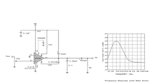
Turbo Bass Circuit

Turbo
Turbo Bass Circuit