Output power: 6W into 4 Ohm load, FET input stage - Passive Tone ControlTiny, portable Guitar Amplifiers are useful for practice on the go and in bedroom/living room environment. Usually, they can be battery powered and feature a headphone output. This project is formed by an FET input circuitry, featuring a High/Low sensitivity switch, followed by a passive Tone Control circuit suitable to Guitar or Bass. After the Volume control, a 6W IC power amplifier follows, powered by a 12-14V dc external supply Adaptor or from batteries, and driving a 4 Ohm 10 or 13cm (4"/5") diameter car loudspeaker. Private listening by means of headphones is also possible.
Circuit diagram:
Mini Guitar-Bass Amplifier Circuit Diagram
Parts:P1______________1M Linear Potentiometer
P2____________100K Log Potentiometer
R1_____________68K 1/4W Resistor
R2____________470K 1/4W Resistor
R3______________2K7 1/4W Resistor
R4______________8K2 1/4W Resistor
R5____________680R 1/4W Resistor
R6____________220K 1/4W Resistor
R7_____________39R 1/4W Resistor
R8______________2R2 1/4W Resistor
R9____________220R 1/4W Resistor
R10_____________1R 1/4W Resistor
R11___________100R 1/2W Resistor
R12_____________1K5 1/4W Resistor
C1____________100pF 63V Polystyrene or Ceramic Capacitor
C2,C5,C9,C14__100nF 63V Polyester Capacitors
C3____________100µF 25V Electrolytic Capacitor
C4_____________47µF 25V Electrolytic Capacitor
C6______________4n7 63V Polyester Capacitor
C7____________470pF 63V Polystyrene or Ceramic Capacitor
C8______________2µ2 25V Electrolytic Capacitor
C10___________470µF 25V Electrolytic Capacitor
C11____________22nF 63V Polyester Capacitor
C12__________2200µF 25V Electrolytic Capacitor
C13__________1000µF 25V Electrolytic Capacitor
D1______________3mm red LED
Q1____________BF245 or 2N3819 General-purpose N-Channel FET
IC1_________TDA2003 10W Car Radio Audio Amplifier IC
SW1,SW2________SPST toggle or slide Switches
J1____________6.3mm Mono Jack socket
J2____________6.3mm Stereo Jack socket (switched)
J3_____________Mini DC Power Socket
SPKR__________4 Ohm Car Loudspeaker 100 or 130mm diameter
Notes:- Connect the output Plug of a 12 - 14V dc 500mA Power Supply Adaptor to J3
- Please note that if the voltage supply will exceed 18V dc the IC will shut down automatically
Technical data:Output power (1KHz sinewave):6W RMS into 4 Ohm at 14.4V supply
Sensitivity:50mV RMS input for full output
Frequency response:25Hz to 20kHz -3dB with the cursor of P1 in center position
Total harmonic distortion:0.05 - 4.5W RMS: 0.15% 6W RMS: 10%
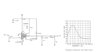
Tone Control Frequency Response: