Showing posts with label driver. Show all posts

Wednesday, November 19, 2014

PWM DC Motor Driver

As the title "PWM DC Motor Driver with Forward / Reverse and Breaking" this series is a PWM DC motor controller that can control DC motors with clockwise rotation and counter-clockwise and is equipped with a braking system. In a series DC motor control PWM DC Motor Driver with Forward / Reverse and Breaking use this system for SASL PWM DC motor rotation speed. Power driver in a series DC motor PWM DC Motor Driver with Forward / Reverse and Breaking uses mosfet IRF150. Then, to control the direction of rotation of DC motor in the circuit of PWM DC Motor Driver with Forward / Reverse and Breaking uses relays. Then the braking system on a series of PWM DC Motor Driver with Forward / Reverse and Breaking is done by a resistor that is connected to the motor using relays.

Fig circuit PWM DC Motor Driver with Forward / Reverse and Breaking


See image details a series of PWM DC Motor Driver with Forward / Reverse and Breaking above. DC motor speed is set to pulse through the input PWM PWM, Power driver uses and the protection mosfet IRF150 with D7 as dumping. Then to start and stop is controlled via the logic input lines provided on the start / stop circuit PWM DC Motor Driver. Line inputs are used to set the reverse direction of rotation of DC motor that is with merberikan logic 1 / 0 on the path. R19 in the circuit of PWM DC Motor Driver serves as an expense to do the braking circle DC motor.

Monday, November 17, 2014

Loudspeaker Driver Circuit

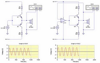
The series of loudspeaker drivers are electronic circuits that function to bridge between high-output circuit with a loudspeaker berimpedasi berimpedansi low. 


Loudspeaker

Why this driver is needed so that the output voltage to be inserted into the loudspeaker is not impaired. Declining value of this voltage is very possible given the lack of rules regarding the distribution of voltage and resistance instead of parallel. Where every prisoner that is placed parallel with other prisoners or the inmates totally substitute for detainee custody is smaller than with individual prisoners themselves. For example, 10 ohm resistance 10 ohms paralleled with the prisoners would get custody instead of 5 ohms. Resistivity 10 ohm to 100,000 ohm paralleled the total resistance is 9.9990 ohms. So it can be concluded that the total voltage will always be smaller than the origin of each detainee. Then, with a decrease in resistance (only using a combination of resistors) or the impedance of the output terminals before, then in accordance with the laws of the voltage divider in series can be ascertained that the prisoners connect in series with output terminal will have a larger part of the voltage and output terminal itself will decline voltage.

The working principle speaker driver circuit is actually very simple and easy to understand. Where the input signal is only used as a trigger to move the second driver transistor to the rhythm of the input signal. While the current that would flow to the loudspeaker most of the power supply driver circuit. You could say similar to the use of transistors as switches. Therefore, in this speaker series driver not found a combination of resistors for reinforcement. So if we look at the picture above, so most of the current flowing in the loudspeaker load is derived from the 9 volt supply voltage, instead of the input ac signal, so that the input signal will not be burdened.

Wednesday, September 24, 2014

Piezo Buzzer Driver Circuit Diagram

  1. Buzzers are small, light, simple to use, and yet provide a loud output signal. They are either of the passive or of the active type.
  2. The former are driven by an AF signal source, while the latter feature a built-in oscillator, and require a direct voltage only. This circuit is a double AF oscillator for driving passive buzzers. It ensures a richer out- put sound than normally obtain- able from a piezo buzzer due to the use of two oscillators, N1 and N2, whose output signal lies between 1 and 10 kHz. Gates Na-N4 form an S-R bistable which is controlled by the out- puts of N1-N2, and drives the buzzer direct.
  3. Optimum effects are achieved when a simple ratio is set between the oscillator frequencies, e.g. 3:4.
  4. Piezoelectric resonators, also referred to as buzzers, are frequently used for providing audible signals in all sorts of electronic equipment.
  5. The spectral l composition of the output X signal is fairly complex, due to the presence of both the fun- damental notes and the differ- ence and sum frequency.
  6. The timbre so obtained varies as a function of the ratio between the oscillator frequencies, which are adjustable with the aid of presets P1-P2. Note that diodes D1-D2 reduce the duty factor of the oscillator signals to about 25%.
  7. The resulting waveform is always composed of rectangular signals, but these differ in respect of their period to ensure that the buzzer pro- duces a rather agreeable sound. The buzzer driver is controlled by a logic level applied to point X. The quiescent current consumption is virtually negligible, while about 10 mA is drawn in the actuated state. 
Buzzer Driver Circuit Diagram


PIC Controlled Relay Driver

This circuit is a relay driver that is based on a PIC16F84A microcontroller. The board includes four relays so this lets us to control four distinct electrical devices. The controlled device may be a heater, a lamp, a computer or a motor. To use this board in the industrial area, the supply part is designed more attentively. To minimize the effects of the ac line noises, a 1:1 line filter transformer is used.

PIC-Controlled-Relay Driver Final
The transformer is a 220V to 12V, 50Hz and 3.6VA PCB type transformer. The model seen in the photo is HRDiemen E3814056. Since it is encapsulated, the transformer is isolated from the external effects. A 250V 400mA glass fuse is used to protect the circuit from damage due to excessive current. A high power device which is connected to the same line may form unwanted high amplitude signals while turning on and off. To bypass this signal effects, a variable resistor (varistor) which has a 20mm diameter is paralelly connected to the input.
 Controller-Schematic Circuit

Another protective component on the AC line is the line filter. It minimizes the noise of the line too. The connection type determines the common or differential mode filtering. The last components in the filtering part are the unpolarized 100nF 630V capacitors. When the frequency increases, the capacitive reactance (Xc) of the capacitor decreases so it has a important role in reducing the high frequency noise effects. To increase the performance, one is connected to the input and the other one is connected to the output of the filtering part.

Supply-Schematic circuit

After the filtering part, a 1A bridge diode is connected to make a full wave rectification. A 2200 uF capacitor then stabilizes the rectified signal. The PIC controller schematic is given in the project file. It contains PIC16F84A microcontroller, NPN transistors, and SPDT type relays. When a relay is energised, it draws about 40mA. As it is seen on the schematic, the relays are connected to the RB0-RB3 pins of the PIC via BC141 transistors. When the transistor gets cut off, a reverse EMF may occur and the transistor may be defected. To overcome this unwanted situation, 1N4007 diodes are connected between the supply and the transistor collectors. There are a few number of resistors in the circuit. They are all radially mounted. Example C and HEX code files are included in the project file. It energizes the next relay after every five seconds.

The components are listed below.
1 x PIC16F84A Microcontroller
1 x 220V/12V 3.6VA (or 3.2VA) PCB Type Transformer (EI 38/13.6)
1 x Line Filter (2x10mH 1:1 Transformer)
4 x 12V Relay (SPDT Type)
4 x BC141 NPN Transistor
5 x 2 Terminal PCB Terminal Block
4 x 1N4007 Diode
1 x 250V Varistor (20mm Diameter)
1 x PCB Fuse Holder
1 x 400mA Fuse
2 x 100nF/630V Unpolarized Capacitor
1 x 220uF/25V Electrolytic Capacitor
1 x 47uF/16V Electrolytic Capacitor
1 x 10uF/16V Electrolytic Capacitor
2 x 330nF/63V Unpolarized Capacitor
1 x 100nF/63V Unpolarized Capacitor
1 x 4MHz Crystal Oscillator
2 x 22pF Capacitor
1 x 18 Pin 2 Way IC Socket
4 x 820 Ohm 1/4W Resistor
1 x 1K 1/4W Resistor
1 x 4.7K 1/4W Resistor
1 x 7805 Voltage Regulator (TO220)
1 x 7812 Voltage Regulator (TO220)
1 x 1A Bridge Diode

http://www.ecircuitslab.com