Showing posts with label 12. Show all posts

Thursday, November 20, 2014

1 3V DC to 12 2V DC Regulator Power Supply

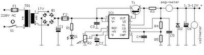
Power supply circuit to generate output below were variations between 1.3V DC to 12.2V DC with 1A current.
In addition, the power supply circuit is also equipped with over-current protection or shield against belebih flow. Power supply circuit is very simple, but the quality is quite good, made her basiskan regulator IC LM723 is a pretty legendary.


1.3V


Description:

R2 to set the output voltage. The maximum current is determined by R3, over-current protection circuit inside the LM723 to detect the voltage on R3, if it reaches 0.65 V, the voltage output will be off her. So the current through R3 can not exceed 0.65 / R3 although output short-circuit in his.

C3 and C4 are ceramic capacitors, as much as possible directly soldered to the PCB, this is because the LM723 is prone to oscillation that is not cool.

LM723 works with 9.5V input voltage to 40 V DC and the LM723 can generate its own current of 150mA when the output voltage is not more than 6-7V under input voltage.


Specifications:

Output (value estimated):

Vmin = (R4 + R5) / (R5 * 1.3)
Vmax = (7.15 / R5) * (R4 + R5)
Imax = 0.65/R3
Max. Power on R3: 0.42/R3


Min. DC Input Voltage (pin 12 to pin 7): Vmax + 5

Component List:

B1 40V/2.5A
C1 2200uF (3300uF even better)
C2 4.7uF
C3 100nF
C4 1NF
C5 330nF
C6 100uF
Green LED D1
D2 1N4003
F1 0.2A F
F2 2A M
IC1 LM723 (in a DIL14 plastic package)
R1 1k
R2 Pot. 5k
R3 0.56R/2W
R4 3.3k
R5 4.7k
S1 250V/1A
T1 2N3055 on a heatsink 5K / W
TR1 220V/17V/1.5

Tuesday, November 18, 2014

6 to 12 Volt Converter

Below its a converter circuit voltage from 6 Volt to 12 Volt DC.

6
6 Volt to 12 Volt DC

Part List :
R1, R4 2 .2K 1/4W Resistor
R2, R3 4.7K 1/4W Resistor
R5 1K 1/4W Resistor
R6 1.5K 1/4W Resistor
R7 33K 1/4W Resistor
R8 10K 1/4W Resistor
C1,C2 0.1uF Ceramic Disc Capacitor
C3 470uF 25V Electrolytic Capcitor
D1 1N914 Diode
D2 1N4004 Diode
D3 12V 400mW Zener Diode
Q1, Q2, Q4 BC547 NPN Transistor
Q3 BD679 NPN Transistor
L1 See Notes
Notes
1. L1 is a custom inductor wound with about 80 turns of 0.5mm magnet wire around a toroidal core with a 40mm outside diameter.

2. Different values of D3 can be used to get different output voltages from about 0.6V to around 30V. Note that at higher voltages the circuit might not perform as well and may not produce as much current. You may also need to use a larger C3 for higher voltages and/or higher currents.

3. You can use a larger value for C3 to provide better filtering.

4. The circuit will require about 2A from the 6V supply to provide the full 800mA at 12V.

Wednesday, September 24, 2014

How to Make 12 9 Volt DC to DC Converter BD139

This circuit is a DC voltage output from a small DC input generate large voltage.It ‘s easy and quick to do, and reducing the value of the Z-diode, the circuit can be universally adapted to other output devices of the circuit voltages. The give and all diagrams represent a DC converter with 12V battery 9 volt DC input and output.
  
12-9 Volt DC to DC Converter Circuit Diagram

With the 10V zener diode, as in the diagram, the output voltage is approximately 9.3 volts DC. The supply voltage is used, should always be at least a few volts higher than the Zener voltage. In this example, I have a 12 Volt DC battery to provide regulated 9-volt DC output. Link