Showing posts with label to. Show all posts

Thursday, November 20, 2014

1 3V DC to 12 2V DC Regulator Power Supply

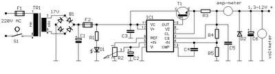
Power supply circuit to generate output below were variations between 1.3V DC to 12.2V DC with 1A current.
In addition, the power supply circuit is also equipped with over-current protection or shield against belebih flow. Power supply circuit is very simple, but the quality is quite good, made her basiskan regulator IC LM723 is a pretty legendary.


1.3V


Description:

R2 to set the output voltage. The maximum current is determined by R3, over-current protection circuit inside the LM723 to detect the voltage on R3, if it reaches 0.65 V, the voltage output will be off her. So the current through R3 can not exceed 0.65 / R3 although output short-circuit in his.

C3 and C4 are ceramic capacitors, as much as possible directly soldered to the PCB, this is because the LM723 is prone to oscillation that is not cool.

LM723 works with 9.5V input voltage to 40 V DC and the LM723 can generate its own current of 150mA when the output voltage is not more than 6-7V under input voltage.


Specifications:

Output (value estimated):

Vmin = (R4 + R5) / (R5 * 1.3)
Vmax = (7.15 / R5) * (R4 + R5)
Imax = 0.65/R3
Max. Power on R3: 0.42/R3


Min. DC Input Voltage (pin 12 to pin 7): Vmax + 5

Component List:

B1 40V/2.5A
C1 2200uF (3300uF even better)
C2 4.7uF
C3 100nF
C4 1NF
C5 330nF
C6 100uF
Green LED D1
D2 1N4003
F1 0.2A F
F2 2A M
IC1 LM723 (in a DIL14 plastic package)
R1 1k
R2 Pot. 5k
R3 0.56R/2W
R4 3.3k
R5 4.7k
S1 250V/1A
T1 2N3055 on a heatsink 5K / W
TR1 220V/17V/1.5

Tuesday, November 18, 2014

6 to 12 Volt Converter

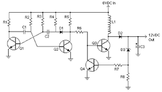
Below its a converter circuit voltage from 6 Volt to 12 Volt DC.

6
6 Volt to 12 Volt DC

Part List :
R1, R4 2 .2K 1/4W Resistor
R2, R3 4.7K 1/4W Resistor
R5 1K 1/4W Resistor
R6 1.5K 1/4W Resistor
R7 33K 1/4W Resistor
R8 10K 1/4W Resistor
C1,C2 0.1uF Ceramic Disc Capacitor
C3 470uF 25V Electrolytic Capcitor
D1 1N914 Diode
D2 1N4004 Diode
D3 12V 400mW Zener Diode
Q1, Q2, Q4 BC547 NPN Transistor
Q3 BD679 NPN Transistor
L1 See Notes
Notes
1. L1 is a custom inductor wound with about 80 turns of 0.5mm magnet wire around a toroidal core with a 40mm outside diameter.

2. Different values of D3 can be used to get different output voltages from about 0.6V to around 30V. Note that at higher voltages the circuit might not perform as well and may not produce as much current. You may also need to use a larger C3 for higher voltages and/or higher currents.

3. You can use a larger value for C3 to provide better filtering.

4. The circuit will require about 2A from the 6V supply to provide the full 800mA at 12V.

Monday, November 17, 2014

IC LM2917 Frequency to Voltage Converter

IC LM2917 IC chip is designed specifically as a Frequency to Voltage Converter or Frequency to Voltage converter. In its use to applications Frequency to Voltage Converter IC LM2917 requires few external components. There are several examples of applications of Frequency to Voltage Converter IC LM2917 datasheet that is included in the LM2917 IC. In this article series Frequency to Voltage Converter IC also taken from the LM2917 datasheet. The advantages of single chip LM2917 Frequency to Voltage Converter is able to provide instantaneous volt output o at time of frequency change 0 Hz. Very easy to apply in measuring the output frequency with the formulation of single-chip Frequency to Voltage Converter VOUT = FIN x VCC x R1 x C1. Then the single-chip LM2917 Frequency to Voltage Converter This configuration requires only the RC only in frequency doubling. And has an internal zener regulator to aimlessly accuracy and stability in frequency-to-voltage conversion process.

Application circuit Figure IC LM2917 as Frequency to Voltage Converter

IC


Feature-owned single-chip LM2917 Frequency to Voltage Converter
Reference to ground directly with variable reluctance
Op Amp / Comparator with transistor output
50 mA maximum output currents for application directly to the load
Frequency doubling for low ripel
Buid in zener
Linear output ± 0.3%
Application single chip LM2917 Frequency to Voltage Converter
Frequency to Voltage Converter
Rotation speed sensor applications
Speedometer
Tachometer
Cruise Control
Cluth Control
And other applications associated with the measurement of rotation speed or frequency measurements.

Tuesday, November 11, 2014

Simple 500W 12V to 220V Inverter


This is a 500W DC-to-AC inverter circuit diagram which produces an AC output at line frequency and voltage. 12VDC to 220V 50Hz inverter circuit will power 220V or 110V appliances from 12V car battery. The circuit is easy to make and is low cost. Use proper transformer. The output (in watts) is up to you by selecting different power rating transformer and power transistor rating. If you load electronic device which require 120V AC, then use transformer with 120V in output 

Monday, November 3, 2014

LM3940 1A Low Dropout Regulator for 5V to 3.3V Conversion

LM3940 1A Low Dropout Regulator for 5V to 3.3V Conversion
General Description :
The LM3940 is a 1A low dropout regulator designed to provide 3.3V from a 5V supply.
The LM3940 is ideally suited for systems which contain both 5V and 3.3V logic, with prime power provided from a 5V bus.
Because the LM3940 is a true low dropout regulator, it can hold its 3.3V output in regulation with input voltages as low as 4.5V.
The T0-220 package of the LM3940 means that in most applications the full 1A of load current can be delivered without using an additional heatsink.
The surface mount TO-263 package uses minimum board space, and gives excellent power dissipation capability when soldered to a copper plane on the PC board.

Features
■ Output voltage specified over temperature
■ Excellent load regulation
■ Guaranteed 1A output current
■ Requires only one external component
■ Built-in protection against excess temperature
■ Short circuit protected
Applications
■ Laptop/Desktop Computers
■ Logic Systems

Typical Application


Connection Diagram


Thursday, October 30, 2014

Inverter Circuit 12VDC to 220V 50Hz 500W

This is circuit Inverter 12VDC to 220V 50Hz 500W.
It easy to make and Low cost. Friends favorite circuit about the the inverter, because like working outdoors, or to backup storage to use when necessary. Most of this is circuit low power, which is not suitable for practical applications. My friends said that he would be about 500 Watt.

It is a good size. Use with television receivers and light bulbs as well. When looking for circuit. I get headaches. If you are a beginner or I can not buy expensive good quality circuits. Requires only one transistor. Or if you have free time. I want to build old circuit is alive again. This circuit will accommodate all your needs. It is a simple circuit. 

Inverter
Inverter 12VDC to 220V 50Hz 500W

The same principle, I take battery voltage 12V to produce a oscillator about 100 Hz and pass to a two frequency divider circuit is only 50HZ. And drive a 10 ampere transformer with 10 x 2N3055 transistor in parallel. By a single transistor has 2A, when I use 10 transistors or 5 pairs of drive high current output. The complexity of circuit, but the principle is not it, and it is the number of transistors on a basic, easy to buy. You may be modified 100 watt power inverter To the size of transistors and transformers as well

1500 W Cobra Power Inverter 12VDC to 120VAC

1500Power Inverter manufactured by Cobra, capable converting input battery 12VDC to become 120VAC with power loads (output) up to 1500W.

This inverter gives household power on the go. It converts battery power to 120 V AC household power, permitting you to power up office equipment and household appliances from your vehicle. This unit is ideal for such appliances as microwave ovens (1000 watts or much less), coffeemakers, laptops, TVs, video game consoles, CD and DVD players, cell phone chargers, and far more.

How The Cobra Power Inverter Works
The Cobra power inverter is an electronic item that has been created and built to take low-voltage DC (Direct Current) power from your automobile or other low-voltage power supplies and convert it to standard 115 volt AC (Alternating Current) power like the current youve inside your residence. This conversion process thereby allows you to make use of numerous of your household appliances and electronic goods in automobiles, RVs, boats, tractors, trucks, and practically anywhere else.

Cobra 1500 Watt Output Waveform
Some quite sensitive electronic equipment could not operate satisfactorily on "square wave" or "modified sine wave" power. The output waveform of the Cobra Inverter is actually a "square wave" or "modified sine wave." It truly is a stepped waveform created to have characteristics similar to the sine wave shape of utility power. A waveform of this nature is suitable for most AC loads, including linear and switching power suppliers used in electronic equipment, transformers, and motors.

AC receptacles
With three ground AC receptacles, you can connect and power multiple devices at as soon as.

USB Output
The 5-Volt USB output permits charging and operation of modern portable devices, for example iPods, BlackBerrys, and cell phones.

Remote On/Off Switch Capable
An optional Remote On/Off Switch could be connected to the Remote Jack, allowing you to turn the Cobra power inverter on or off from a convenient location when the inverter is installed out of reach.

Safety Features
The CPI 1575 will notify you with a flashing meter and alarm sound when there is a power issue, and will shut down for protection in the following situations:

  • Current Overload Protection--If the inverter is overloaded, itll shut down to protect itself.
  • Short Circuit Protection--If the AC output of the inverter is short-circuited for 1 second or more, it is going to shut down to safeguard itself.
  • Low Voltage Protection--If the input voltage drops to 10.0V or much less, the inverter will shut down to protect itself.
  • High Voltage Protection--If the DC input voltage rises above 15.0V, the inverter will shut down to safeguard itself.
  • Over Temperature Protection--If the internal temperature rises to 40 degrees C (104 degrees F), the inverter will shut down to safeguard itself. 

Saturday, October 25, 2014

How to build Power Flip Flop Using A Triac

Modern electronics is indispensable for every large model railroad system, and it provides a solution to almost every problem. Although ready-made products are exorbitantly expensive, clever electronics hobbyists try to use a minimum number of components to achieve optimum results together with low costs. This approach can be demonstrated using the rather unusual semiconductor power flip-flop described here. A flip-flop is a toggling circuit with two stable switching states (bistable multivibrator). It maintains its output state even in the absence of an input pulse.

Flip-flops can easily be implemented using triacs if no DC voltage is available. Triacs are also so inexpensive that they are often used by model railway builders as semiconductor power switches. The decisive advantage of triacs is that they are bi-directional, which means they can be triggered during both the positive and the negative half-cycle by applying an AC voltage to the gate electrode (G). The polarity of the trigger voltage is thus irrelevant. Triggering with a DC current is also possible. Figure 1 shows the circuit diagram of such a power flop-flop. A permanent magnet is fitted to the model train, and when it travels from left to right, the magnet switches the flip-flop on and off via reed switches S1 and S2.

Circuit diagram:

In order for this to work in both directions of travel, another pair of reed switches (S3 and S4) is connected in parallel with S1 and S2. Briefly closing S1 or S3 triggers the triac. The RC network C1/R2, which acts as a phase shifter, maintains the trigger current. The current through R2, C1 and the gate electrode (G) reaches its maximum value when the voltage across the load passes through zero. This causes the triac to be triggered anew for each half-cycle, even though no pulse is present at the gate. It remains triggered until S2 or S4 is closed, which causes it to return to the blocking state.The load can be incandescent lamps in the station area (platform lighting) or a

solenoid-operated device, such as a crossing gate. The LED connected across the output (with a rectifier diode) indicates the state of the flip-flop. The circuit shown here is designed for use in a model railway system, but there is no reason why it could not be used for other applications. The reed switches can also be replaced by normal pushbutton switches. For the commonly used TIC206D triac, which has a maximum current rating of 4 A, no heat sink is necessary in this application unless a load current exceeding 1 A must be supplied continuously or for an extended period of time. If the switch-on or switch-off pulse proves to be inadequate, the value of electrolytic capacitor C1 must be increased slightly.
Author: R. Edlinger - Copyright: Elektor July-August 2004

How to build Personal alarm

Small, portable, anti-bag-snatching unit Also suitable for doors and windows control

Circuit diagram


Parts:

  • R1 330K 1/4W Resistor
  • R2 100R 1/4W Resistor
  • C1 10nF 63V Polyester or Ceramic Capacitor
  • C2 100µF 25V Electrolytic Capacitor
  • Q1 BC547 45V 100mA NPN Transistor
  • Q2 BC327 45V 800mA PNP Transistor
  • SW1 Reed Switch and small magnet (See Notes)
  • SPKR 8 Ohm Loudspeaker (See Notes)
  • B1 3V Battery (two A or AA cells wired in series etc.)

Device purpose:

This circuit, enclosed in a small plastic box, can be placed into a bag or handbag. A small magnet is placed close to the reed switch and connected to the hand or the clothes of the person carrying the bag by means of a tiny cord. If the bag is snatched abruptly, the magnet looses its contact with the reed switch, SW1 opens, the circuit starts oscillating and the loudspeaker emits a loud alarm sound. The device can be reverse connected, i.e. the box can be placed in a pocket and the cord connected to the bag. This device can be very useful in signalling the opening of a door or window: place the box on the frame and the magnet on the movable part in a way that magnet and reed switch are very close when the door or window is closed.

Circuit operation:

A complementary transistor-pair is wired as a high efficiency oscillator, directly driving a small loudspeaker. Low part-count and 3V battery supply enable a very compact construction.

Notes:

  • The loudspeaker can be any type, its dimensions are limited only by the box that will contain it.
  • An on-off switch is unnecessary because the stand-by current drawing is less than 20µA.
  • Current consumption when the alarm is sounding is about 100mA.
  • If the circuit is used as anti-bag-snatching, SW1 can be replaced by a 3.5mm mono Jack socket and the magnet by a 3.5mm. mono Jack plug with its internal leads shorted. The Jack plug will be connected with the tiny cord etc.
  • Do not supply this circuit with voltages exceeding 4.5V: it will not work and Q2 could be damaged. In any case a 3V supply is the best compromise.

Wednesday, September 24, 2014

How to Build 1 2 30V 1 5A Variable Regulated Power supply Circuit


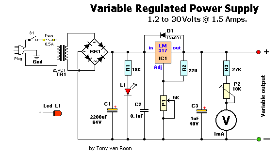
How to Build 1.2-30V/1.5A Variable Regulated Power supply, This is simple 1.2-30V/1.5A variable regulated power supply circuit diagram The 110V-AC coming from the powercord is fed to the transformer TR1 via the on-off switch and the 500mA fuse. The 30vac output (approximately) from the transformer is presented to the BR1, the bridge-rectifier, and here rectified from AC (Alternating Current) to DC (Direct Current). If you dont want to spend the money for a Bridge Rectifier, you can easily use four general purpose 1N4004 diodes. The pulsating DC output is filtered via the 2200µF capacitor (to make it more manageable for the regulator) and fed to IN-put of the adjustable LM317 regulator (IC1). The output of this regulator is your adjustable voltage of 1.2 to 30volts varied via the Adj pin and the 5K potmeter P1. The large value of C1 makes for a good, low ripple output voltage.

 1.2-30V/1.5A Variable Regulated Power supply Circuit Diagram

1.2-30V/1.5A Variable Regulated Power supply Circuit


Why exactly 1.2V and not 0-volt? Very basic, the job of the regulator is two-fold; first, it compares the output voltage to an internal reference and controls the output voltage so that it remains constant, and second, it provides a method for adjusting the output voltage to the level you want by using a potentriometer. Internally the regulator uses a zener diode to provide a fixed reference voltage of 1.2 volt across the external resistor R2. (This resistor is usually around 240 ohms, but 220 ohms will work fine without any problems). Because of this the voltage at the output can never decrease below 1.2 volts, but as the potentiometer (P1) increases in resistance the voltage accross it, due to current from the regulator plus current from R2, its voltage increases. This increases the output voltage.

D1 is a general purpose 1N4001 diode, used as a feedback blocker. It steers any current that might be coming from the device under power around the regulator to prevent the regulator from being damaged. Such reverse currents usually occur when devices are powered down.

The ON Led will be lit via the 18K resistor R1. The current through the led will be between 12 - 20mA @ 2V depending on the type and color Led you are using. C2 is a 0.1µF (100nF) decoupler capacitor to filter out the transient noise which can be induced into the supply by stray magnetic fields. Under normal conditions this capacitor is only required if the regulator is far away from the filter cap, but I added it anyway. C3 improves transient response. This means that while the regulator may perform perfectly at DC and at low frequencies, (regulating the voltage regardless of the load current), at higher frequencies it may be less effective. Adding this 1 µF capacitor should improve the response at those frequencies.

R3 and the trimmer pot (P2) alows you to zero your meter to a set voltage. The meter is a 30Volt type with an internal resistance of 85 ohms. I you have or obtained a meter with a different Ri (internal resistance) you will have to adjust R3 to keep the current of meter to 1mA. Just another note in regards this meter, use the reading as a guideline. The reading may or may not be off by about 0.75volts at full scale, meaning if your meter indicates 30 volts it may be in reality almost 31 volts or 29 volts. If you need a more precies voltage, then use your multimeter.


Construction:
Because of the few components you can use a small case but use whatever you have available. I used a power cord from a computer and cut the computer end off. All computer power cords are three-prong. The ground wire, which is connected to the middle pin of the power plug is connected to the chassis. The color of the ground-wire is either green or green/yellow. It is there for your protection if the 110vac accidentally comes in contact with the supply housing (case). BE CAREFUL always to disconnect the powerplug when you working inside the chassis. If you choose to use an in-line, or clip-type fuseholder be sure to isolate it with heat shrink or something to minimize accidental touching.

I use perf-board (or Vero board) as a circuit board. This stuff is widely available and comes relatively cheap. It is either made of some sort of fiber material or Phenolic or Bakelite pcb. They all work great. Some Phenolic boards come with copper tracks already on them which will make soldering the project together easier.

I mounted the LM317(T) regulator on a heatsink. If you use a metal/aluminum case you can mount it right to the metal case, insulated with the mica insulator and the nylon washer around the mounting screw. Note that the metal tab of the LM317 is connected internally to the Output pin. So it has to be insulated when mounting directly to the case. Use heat sink compound (comes in transparent or white color) on the metal tab and mica insulator to maximize proper heat transfer between LM317 and case/ or heatsink.

Drill the holes for the banana jacks, on/off switch, and LED and make the cut-out for the meter. It is best to mount everything in such a way that you are able to trouble-shoot your circuit board with ease if needed. One more note about the on-off switch S1, this switch has 110VAC power to it. After soldering, insulate the bare spots with a bit of silicon gel. Works great and prevents electrical shock through accidental touching.

If all is well, and you are finished assembling and soldering everything, check all connections. Check capacitors C1 & C3 for proper polarity (especially for C1, polarity reversal may cause explosion). Hookup a multimeter to the power supply output jacks. Set the meter for DC volts. Switch on S1 (led will light, no smoke or sparks?) and watch the meter movement. Adjust the potentiometer until it reads on your multimeter 15Volts. Adjust trimpot P2 until the meter also reads 15volts. When done, note any discrepancies between your multimeter and the power supply meter at full scale (max output). Maybe there is none, maybe there is a little, but you will be aware of it. Good luck and have fun building!


Parts List

BR1 = Bridge Rectifier, 100V - 3A       C1 = 2200 µF, 63V
IC1 = LM317, adjustable regulator       C2 = 0.1 µF
  V = Meter, 30V, Ri = 85 ohm           C3 = 1µF, 40V
TR1 = Transformer, 25V, 2A            Plug = 3-wire plug & cord
 R1 = 18K, 5%                           S1 = On-Off toggle switch
 R2 = 220 ohm, 5%                       D1 = 1N4001
 R3 = 27K, 5%                         Fuse = 110V, 500mA, slow-blow
 P1 = 5K, potentiometer               FuseHolder, wire, solder, case, knob for P1
 P2 = 10K, 10-turn trim-pot           Red & Black Banana Jacks

Notes:  
This is a simple, but low-ripple powersupply, and an excellent project if youre starting out in electronics. It will suit your needs for most of your bench testing and prototype applications. The output is adjustable from 1.2 volts to about 30 volts. Maximum current is about 1.5 amps which is also sufficient for most of your tinkering. It is relatively easy to build and can be pretty cheap if you have some or all the required parts. A printed circuit board is not included and Im not planning on adding one since the whole thing can easily be build on perferated or vero board. Or buy one of Radio Shack/Tandys experimentors boards (#276-150). Suit yourself. The meter and the transformer are the money suckers, but if you can scrounge them up from somewhere it will reduce the cost significantly. BR1 is a full-wave bridge rectifier. The two ~ denotes AC and are connected to the 25vac output coming from the transformer. IC1 is a 3-pin, TO-220 model. Be sure to put a cooling rib on IC1, at its max 1.5 A current it quickly becomes very hot..

All the parts can be obtained from your local Radio Shack or Tandy store. The physical size of the power supply case depends largely on the size of the meter & transformer. But almost anything will do. Go wild.


Sourced By  Tony  van roon
How to Make 12 9 Volt DC to DC Converter BD139

This circuit is a DC voltage output from a small DC input generate large voltage.It ‘s easy and quick to do, and reducing the value of the Z-diode, the circuit can be universally adapted to other output devices of the circuit voltages. The give and all diagrams represent a DC converter with 12V battery 9 volt DC input and output.
  
12-9 Volt DC to DC Converter Circuit Diagram

With the 10V zener diode, as in the diagram, the output voltage is approximately 9.3 volts DC. The supply voltage is used, should always be at least a few volts higher than the Zener voltage. In this example, I have a 12 Volt DC battery to provide regulated 9-volt DC output. Link