Showing posts with label 555. Show all posts

Thursday, November 13, 2014

555 timer bassed Metal detector circuit with explanation

A very simple metal detector electronic project can be designed using a simple 555 timer integrated circuit . As you can see in the schematic circuit , this electronic project requires few external electronic parts .

This circuit detects metal and also magnets. When a magnet is brought close to the 10mH choke, the output frequency changes.
This metal detector project can be powered from a power supply that can provide an output DC voltage between 6 an 12 volt .
If a metal is closer to the L1 coil , will produce a change of output oscillation frequency, that will generate a sound in the 8 ohms speaker .

Metal

readmore: electroniq.net/other-projects/detectors/metal-detector-using-555-timer-circuit.html

Saturday, October 25, 2014

Using 555 Timer Voltage Controlled Switch


In this circuit the 555 timer is used in a novel way, as a voltage controlled switch.The old and omnipresent NE555 can be very good at something it was not meant for: driving relays or other loads up to 200 mA. The picture shows an example circuit: if the input level rises over 2/3 of the supply voltage - it will turn on the relay, and the relay will stay on until the level at the input drops below one third of the supply voltage.

If the relay and D1 were connected between pin 3 and ground, the relay would be activated when the input voltage drops below one third, and deactivated when the input voltage goes over two thirds of the supply voltage. It is also a nice advantage that the input requires only about 1 uA, which is something bipolar transistors cant compete with. (This high impedance input must not be left open.) A large hysteresis makes the circuit immune to noise. The output (pin 3) can only be either high or low (voltage-wise), and it changes its state almost instantenously, regardless of the input signal shape.


The voltage drop across the NE555s output stage (at 35-100 mA) is 0.3-2.0 V, depending on the way the relay is connected and the exact current it draws. D1 is absolutely vital to the safety of the integrated circuit.

Extend Timer Range For The 555

Anyone who has designed circuits using the 555 timer chip will, at some time have wished that it could be programmed for longer timing periods. Timing periods greater than a few minutes are difficult to achieve because component leakage currents in large timing capacitors become significant. There is however no reason to opt for a purely digital solution just yet. The circuit shown here uses a 555 timer in the design but nevertheless achieves a timing interval of up to an hour! The trick here is to feed the timing capacitor not with a constant voltage but with a pulsed dc voltage. The pulses are derived from the un smoothed low voltage output of the power supply bridge rectifier.


The power supply output is not referenced to earth potential and the pulsing full wave rectified signal is fed to the base of T1 via resistor R1. A 100-Hz square wave signal is produced on the collector of T1 as the transistor switches. The positive half of this waveform charges up the timing capacitor C1 via D2 and P1. Diode D2 prevents the charge on C1 from discharging through T1 when the square wave signal goes low. Push-button S1 is used to start the timing period. This method of charging uses relatively low component values for P1 (2.2 MΩ) and C1 (100 to 200 µF) but achieves timing periods of up to an hour which is much longer than a standard 555 circuit configuration.

Wednesday, October 1, 2014

Simple Function Generator Circuit Using IC 555

This circuit of a simple function generator circuit explained here generates sawtooth and triangle waveforms at a frequency set by an external control voltage. Current source Ol draws a current l from timing capacitor C.
Simultaneously current source O2 draws the same current from current mirror O3, O4; this is set up (by R1 and R2) to deliver (from the collector of O4) twice the current leaving O2. Hence C receives a current 2 l from the top rail, at the same time delivering l to the bottom rail, the net effect being that the capacitor is charged by a constant current l, its voltage rising linearly until the 555s upper trigger point (at 2/3Vcc) is reached. - The output (pin 3) then goes low, as does the open~collector discharge output at pin 7.

 The latter shunts the output of the current mirror to earth, D1 becoming reverse-biased and isolating C. Now only current source O1 is connected to the timing capacitor which is now linearly discharged by current I. ln this way C is alternately charged and discharged. When the voltage on C falls to the 555s lower trigger point at 1/3Vcc, the output and discharge pins go high, and the  cycle recommences; the repetition frequency is determined by the magnitude of I, which is set by the voltage applied at the input point A. With the component values shown, the frequency range is from approx.  2.5 kHz to less than 10 Hz, as the control voltage varies from +10 V to zero; the frequency is directly proportional to the control voltage. Other ranges may be obtained by altering the value of C.


Wednesday, September 24, 2014

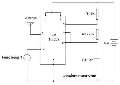
Using 555 as FM transmitter Circuit Diagram

The integrated circuit 555 has no limits, this FM transmitter circuit, the IC 555 is designed as an stable multivibrator as usual. But the tension control pin is used to connect a piezoelectric element instead of the capacitor disk. The piezoelectric element generates a voltage and the output pin is connected to an antenna wire 30 inches for the transmission of signals.Just tap the piezo element and you can hear the sound on an FM radio station. The range is very short.


Using 555 as FM transmitter Circuit Diagram

Using 555 as FM transmitter Circuit Diagram