Showing posts with label battery. Show all posts

Tuesday, November 11, 2014

Versatile Micropower Battery Protector

Protect your expensive batteries from discharge damage with this mini-sized electronic cutout switch. It uses virtually no power and can be built to suit a wide range of battery voltages.
Main Features
  • Disconnects load at preset battery voltage
  • Automatically reconnects load when battery recharged
  • Ultra-low power consumption (<20ma)
  • Miniature size
  • 10A maximum rating
  • Suitable for use with 4.8-12.5V batteries
  • Transient voltage protection (optional)
  • Suitable for use in...
    • Cars, boats & caravans
    • Security systems
    • Emergency lighting
    • Small solar installations
    • Camera battery packs
    • Many other low-power applications
    Picture of the project:
    versatile-micropower-battery-protector-circuit1


    Back in May 2002, we (Silicon Chip) presented the "Battery Guardian", a project designed specifically for protecting 12V car batteries from over-discharge. This unit has proven to be very popular and is still available from kit suppliers. This new design does not supersede the Battery Guardian – at least not when it comes to 12V car batteries. Instead, it’s a more flexible alternative that can be used with a wide range of battery voltages.

    Parts layout:


    In this new "Micropower Battery Protector", we’ve dispensed with the low-battery warning circuitry and the relatively cheap N-channel MOSFET used in the Battery Guardian in favour of a physically smaller module that steals much less battery power. It costs a little more but can switch lower voltages, allowing it to be used with 6V & 12V lead-acid batteries and 4-cell to 10-cell NiCd and NiMH battery packs.

    PCB layout:

    Most battery-powered equipment provides no mechanism for disconnecting the batteries when they’re exhausted. Even when the voltage drops too low for normal operation, battery drain usually continues until all available energy is expended. This is particularly true of equipment designed to be powered from alkaline or carbon cells but retro-fitted with rechargeables.

    Circuit diagram:


    Another example is emergency lighting and security equipment designed to be float-charged from the mains. In an extended blackout period, the batteries can be completely drained and may not recover when the mains power is finally restored.
    Source: Silicon Chip 27 July 2004

Thursday, November 6, 2014

5v Powered Charge Pump Battery Charger

The circuit below will trickle charge a four cell pack of AA or AAA NiMH batteries.  The circuit draws current from the +5v available a USB connection and pumps about 70ma of current into the battery. This should be enough current to fully charge a pack of 2500ma-hour cells in about 36 hours.  The circuit uses a single 74HC14 hex Schmitt trigger inverter in conjunction with a voltage doubler charge pump circuit.

Wednesday, November 5, 2014

Lead Acid Battery Protector

The circuit described here can be used to  ensure  that  a  12 V  sealed  lead  acid  (SLA)  gel battery isn’t discharged too deeply. The  principal part of the circuit is a bistable relay,  which is driven by the output of an op amp.

Lead Acid Battery Protector Circuit Diagram:


The battery voltage is first reduced via D1, R1,  P1 and R2, and then continuously compared  with a reference voltage set up by diode D2.  When the battery discharges too much and  its terminal voltage drops below the level  set by P1, the output of the opamp becomes  High, which causes the relay to toggle. This  in turn isolates the load from the battery. The  battery can be reconnected via S1 once the  battery has been replaced or recharged.

The relay used in the prototype is a 5 V bistable type made by Omron (G6AK-234P-ST-US  5 VDC). The two windings of the relay each  have a resistance of 139 Ω (for the RAL-D 5  W-K made by Fujitsu this is 167 Ω). When the  battery voltage starts to become too low and  the relay is being reset the current consumption of the circuit is about 45 mA. Shortly  after the load has been disconnected, when the battery voltage rises above the reference  voltage again, the reset coil will no longer be  powered and the current consumption drops  back to about 2.5 mA.

The range of P1 has intentionally been kept  small. With a reference voltage of 5.6 V (D2)  and a voltage drop of 0.64 V across D1, the circuit reacts within a voltage span of 11.5 V and  11.8 V. This range is obviously dependent on the zener diode used and the tolerance.

For a greater span you can use a larger value  for P1 without any problems. With the potentiometer at its mid setting the circuit switches  at about 11.6 V.

Tuesday, November 4, 2014

Car Battery 12v Charger

The usual chargers of battery automotive, are simple and cheap appliances that charge continuously the battery, with a rythm of few amperes, for the time where the appliance is ON. If the holder do not close in time the charger, the battery will overcharge and her electrolytic faculty are lost with evaporation or likely exists destruction of her elements. The charger of circuit exceeds these faults. It checks electronic the situation of charge of battery and it has circuit of control with retroaction, that forces the battery charge with biggest rythm until charge completely. 

Car Battery 12v Charger Circuit diagram:
 
Charger

When charge completely, it turns on one RED led (LD2). The charger has been drawn in order to charge batteries of 12V, ONLY. What should watch it from what it manufactures the circuit, they are the cables that connect the transformer with the circuit and in the continuity the battery, should they are big cross-section, so that heat when it passes from in them the current of charge and also they do not cause fall of voltage at the way of current through them.
 
Adjustment:
 
After assembling of the circuit, adjust TR1 to null value, power-up and make the following adjustments :-
  1. Without connecting the battery check that the 2 LED?s are turned on.
  2. Connect a car battery to the circuit and check that LD2 is OFF and a current (normally 2A to 4A) is flowing to the battery.
  3. Adjust TR1 until LD2 turns ON and the charge current is cut.
  4. Adjust TR1 to null value and charge the battery using the hydrometer technique (if you do not have or do not know how to use a hydrometer, then use a good condition battery and charge).

Carefully adjust TR1 so that LD2 begins to turn ON and the charge current falls to a few hundred milliamps (mA). If TR1 is set correctly then in the next round of charging you will noticed LD2 begin to flicker as the battery is being charged. When battery is completely charged, LD2 turns ON completely.TR1 does not need further adjustment anymore. Q1 is connected in line with the battery and is fired by R3, R4 and LD2. The R2, C1, TR1 and D2 sense the voltage of the battery terminal and activate Q2 when the voltage of the battery terminal exceeds the value predetermined by TR1.

When an uncharged battery is connected, the terminal voltage is low. Under this circumstance, Q2 is turned OFF and Q1 is fired in each half cycle by R3, R4 and LD2. The Q1 functions as a simple rectifier and charges the battery. If the battery terminal voltage is increased above the level that had been fixed by TR1, then Q2 shifts the control of Q1 gate. This deactivates Q1 and cuts off the current supply to the battery and turns LD2 ON indicating that the charge has been completed. Q1 and bridge rectifier GR1 should be mounted on heatsinks to prevent overheating. M1 is a 5A DC ammeter to measure the charge current.


Saturday, October 25, 2014

Build a Smart battery charger

This is a smart battery charger can protect your vehicles battery from failing and will prolong its life – theyre fully automatic so you can connect and forget.


Build a Smart battery charger

This is a smart battery charger can protect your vehicles battery from failing and will prolong its life – theyre fully automatic so you can connect and forget.


Simple NiCd Battery Charger

The design of the charger is similar to that of many commercially available chargers. The charger consists of a mains adaptor, two resistors and a light-emitting diode (LED). In practical use, this kind of charger is perfectly all right. Resistor R1 serves two functions: it establishes the correct charging current and it drops sufficient voltage to light the diode. This means that the LED lights only when a charging current flows into the battery. The charging current is about 1/4 of the battery capacity, which allows a slight overcharging, and yet the charging cycle is not too long (4–5 hours).


The value of the resistors may be calculated as follows, for which the nominal e.m.f. and the capacity of the battery must be known. Adjust the output of the mains adaptor to 1.17 times the nominal battery voltage plus 3.3 V, which is the potential across R1. Note that the adaptor must be capable of supplying a current of not less than half the battery capacity. The value of R1 in ohms is equal to 3.3 divided by 1/4 of the battery capacity. The value of the resistors for various battery voltages is given in the Table. The battery capacity is taken as 1 Ah.

NiCd Battery Charger Circuit DiagramThe rating of R1 should be 5 W. If the battery to be charged has a different capacity, the theoretical value of R1 in the table must be divided by the battery capacity. Its actual value is the nearest one in the E12 series. For instance, if a 6 V battery with a nominal capacity of 600 mAh is to be charged, the value of R1 must be 20/0.6 = 33R.

Wednesday, September 24, 2014

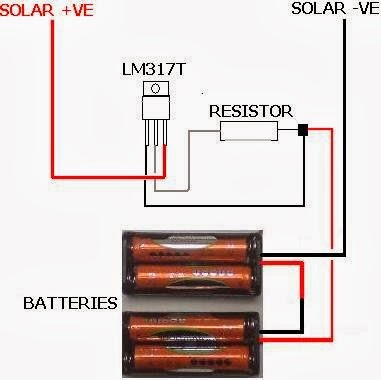
Simple Solar Battery Charger with LM317 Circuit Diagram

Simple Solar Battery Charger with LM317 Circuit Diagram. This is a solar panel battery charger schematic for AA and AAA rechargeable batteries. A small solar panel would be very good as a source of voltage charger. Building a solar AA battery charger only requires a few components and a simple construction. Solar panels should be well adapted to the battery to be charged or the battery may be overcharged. 

If you want to charge batteries with different capacities, then you need to change the solar panels. Since this is a simple solar battery charger that does not automatically turn off when the battery is full. So we need to maintain the charging current is low enough that will not damage the battery even when they are fully charged. An LM317T voltage regulator chip that can be used with a suitable resistor to regulate current. See solar AA battery charger 

 Solar Battery Charger with LM317 Circuit Diagram

 Solar Battery Charger with LM317 Circuit Diagram


Car Battery 12v Charger

The usual chargers of battery automotive, are simple and cheap appliances that charge continuously the battery, with a rythm of few amperes, for the time where the appliance is ON. If the holder do not close in time the charger, the battery will overcharge and her electrolytic faculty are lost with evaporation or likely exists destruction of her elements. The charger of circuit exceeds these faults. It checks electronic the situation of charge of battery and it has circuit of control with retroaction, that forces the battery charge with biggest rythm until charge completely.
Circuit diagram:
Car_baterry_charger Circuit Diagram
Car Battery 12v Charger Circuit Diaram
When charge completely, it turns on one RED led (LD2). The charger has been drawn in order to charge batteries of 12V, ONLY. What should watch it from what it manufactures the circuit, they are the cables that connect the transformer with the circuit and in the continuity the battery, should they are big cross-section, so that heat when it passes from in them the current of charge and also they do not cause fall of voltage at the way of current through them.
Adjustment
After assembling of the circuit, adjust TR1 to null value, power-up and make the following adjustments :-
  1. Without connecting the battery check that the 2 LED?s are turned on.
  2. Connect a car battery to the circuit and check that LD2 is OFF and a current (normally 2A to 4A) is flowing to the battery.
  3. Adjust TR1 until LD2 turns ON and the charge current is cut.
  4. Adjust TR1 to null value and charge the battery using the hydrometer technique (if you do not have or do not know how to use a hydrometer, then use a good condition battery and charge).

Carefully adjust TR1 so that LD2 begins to turn ON and the charge current falls to a few hundred milliamps (mA). If TR1 is set correctly then in the next round of charging you will noticed LD2 begin to flicker as the battery is being charged. When battery is completely charged, LD2 turns ON completely.TR1 does not need further adjustment anymore. Q1 is connected in line with the battery and is fired by R3, R4 and LD2. The R2, C1, TR1 and D2 sense the voltage of the battery terminal and activate Q2 when the voltage of the battery terminal exceeds the value predetermined by TR1.

When an uncharged battery is connected, the terminal voltage is low. Under this circumstance, Q2 is turned OFF and Q1 is fired in each half cycle by R3, R4 and LD2. The Q1 functions as a simple rectifier and charges the battery. If the battery terminal voltage is increased above the level that had been fixed by TR1, then Q2 shifts the control of Q1 gate. This deactivates Q1 and cuts off the current supply to the battery and turns LD2 ON indicating that the charge has been completed. Q1 and bridge rectifier GR1 should be mounted on heatsinks to prevent overheating. M1 is a 5A DC ammeter to measure the charge current.

Source :users.otenet.gr

A Car Battery Monitor

A close call on the road can really focus your mind on the importance of having a battery monitor in a car. I had been enjoying a pleasant week of travelling around the countryside at a leisurely pace and taking in the beautiful scenery each day. It wasnt until the final day, with the big rush to return home, that I had to drive at night.My home is deep in the country and on the road I was travelling the closest petrol station may be 80km away. I was travelling through an area that is full of open-cut coal mines and large heavily loaded semi-trailers constantly pound the roads, travelling at quite high speeds. It was around 8pm at night and everything was very dark no street lights or house lights anywhere.

Just as I was going up a hill, the lights began to dim and the engine coughed. A large semi-trailer loomed in the rear-vision mirror as I pushed the clutch in and tried to restart. My speed was falling rapidly and my lights were blacked out - I was like a sitting duck in the middle of the road, as the semi-trailer came rapidly bearing down on me. I just managed to pull the car off the road, as the semi-trailer came screaming past, missing me by inches! After calling for assistance from the NRMA, the problem was found to be a fault in the alternator, which was failing to charge the battery. The battery voltage had been falling under the heavy load of the lights and at the worst possible time, there was not sufficient power for the lights or the motor.

After the initial shock wore off, I put on my thinking cap to come up with a PIC-based solution to the problem. What was really needed was a display and a buzzer, to get my attention should the voltage fall outside a specified range. So my design criteria was set, a series of LEDs could indicate the voltage and a buzzer would also be used to warn of problems.
Main Features:
  • Visual indication of battery voltage
  • Audible warning when voltage becomes low
  • Screw terminals for easy connection
  • Simple and easy to build
Circuit details:

The circuit is based on PIC16F819 18-pin microcontroller which has an analog-to-digital (A/D) input to monitor the battery voltage and outputs capable of driving LEDs directly, to keep the component count down. There are seven LEDs in all, giving a good range of voltage indication. The topmost LED, LED1, comes on for voltages above 14V which will occur when the battery is fully charged. LED2 indicates for voltages between 13.5V and 14V while LED3 indicates between 13V and 13.5V. Normally, one of these LEDs will be on. LED4 covers 12.5V to 13V while LED5 covers 12V to 12.5V. LED6 covers from 11.5V to 12V while LED7 comes on for voltages below 11.5V. These two LEDs are backed up by the piezo chime which beeps for voltages between 11.5V and 12V and becomes more insistent for voltages below 11.5V.

That might seem fairly conservative. After all, most cars will start with no troubles, even though the battery voltage might be a touch below 12V, wont they? Well, no. Some modern cars will happily crank the motor at voltages below 11V but their engine management will not let the motor start unless the voltage is above 11V. So dont think that a modern car will always start reliably. This little battery monitor could easily prevent a very inconvenient failure to start! So lets describe the rest of the circuit. The incoming supply is connected via diode D1 which provides protection against reverse polarity while zener diode ZD1 provides protection from spike voltages.

A standard 7805 3-terminal regulator is then used to provide a stable 5V to the microcontroller. The battery voltage is sensed via a voltage divider using 33kΩ and 100kΩ resistors. This brings the voltage down to within the 0-5V range for the A/D input of the PIC16F819. Port B (RB0 to RB7) of the microcontroller is then used to drive the various LEDs, with current limiting provided via the 330Ω resistor network. RB7, pin 13, drives a switching transistor for the piezo buzzer.

Software:
For the software, the design follows the basic template for a PIC microcontroller. Port A and its ADC (analog-to-digital converter) function are set up while port B functions as the output for the LEDs and buzzer. Once the set-up is complete, a reading will be taken at port RA2, the input for the A/D convertor. This reading is then compared with a series of values to determine the range of the voltage. This is similar to a series of "if" statements in Basic language. If the voltage is found to be within a certain range, the relevant port B pin will be turned on. If the voltage is below 12V, the buzzer will be turned on for a brief period, to signal a low battery condition. As the voltage falls below 11.5V, the frequency of the beeps will increase, to signal increased urgency.

Building it:

All the parts are mounted on a small PC board measuring 46 x 46mm (available from Futurlec). The starting point should be the IC socket for the PIC16F819, as this is easiest to mount while the board is bare. The next item can be the PC terminal block. The resistors and capacitors can then follow. Make sure the electrolytics are inserted with correct polarity.

Make sure that you do not confuse the zener (ZD1) with the diode when you are installing them; the diode is the larger package of the two.
 
Even more important, dont get the 78L05 3-terminal regulator and the 2N3906 transistor mixed up; they come in identical packages. The 78L05 will be labelled as such while the 2N3906 will be labelled "3906". And make sure you insert them the correct way around. The buzzer must also be installed with the correct polarity. The 330Ω current limiting resistors are all in a 10-pin in-line package. There are four green LEDs, two yellow and one red. They need to be installed in line and with the correct orientation.

Testing:

Before you insert the PIC16F819 microcontroller, do a voltage check. Connect a 12V source and check for the presence of 5V between pins 14 & 5 OF IC1. If 5V is not present, check the polarity of regulator REG1 and the polarity of the diode D1. If these tests are OK, insert the IC and test the unit over a range of voltage between 9V and 15V. Make sure that all LEDs come on in sequence and the piezo buzzer beeps for voltages below 12V. 

Now it is matter of installing the unit in your car. It is preferable to install the unit in a visible position for the driver. However, it should not obscure any other instruments. The unit should be connected to the cars 12V supply after the ignition switch. This will turn the unit off with the other instruments and prevent battery drain while the motor is not running.


Author :Alan Bonnard Copyright : Silicon Chip Publications Pty Ltd

Simple Lead Acid Battery Charger 2

The above pictured schematic diagram is just a standard constant current model with a added current limiter, consisting of Q1, R1, and R4. The moment too much current is flowing biases Q1 and drops the output voltage. The output voltage is: 1.2 x (P1+R2+R3)/R3 volt. Current limiting kicks in when the current is about 0.6/R1 amp. For a 6-volt battery which requires fast-charging, the charge voltage is 3 x 2.45 = 7.35 V. (3 cells at 2.45v per cell). So the total value for R2 + P1 is then about 585 ohm. For a 12 V battery the value for R2 + P1 is then about 1290 ohm. 

For this power supply to work efficiently, the input voltage has to be a minimum of 3V higher than the output voltage. P1 is a standard trimmer potentiometer of sufficient watt for your application. The LM317 must be cooled on a sufficient (large) coolrib. Q1 (BC140) can be replaced with a NTE128 or the older ECG128 (same company). Except as a charger, this circuit can also be used as a regular power supply.

Lead Acid Battery Charger circuit diagramBattery ChargerBattery ChargerParts List:

R1 = 0.56 Ohm, 5W, WW
R2 = 470 Ohm C2 = 220nF
R3 = 120 Ohm
R4 = 100 Ohm
C1 = 1000uF/63V
Q1 = BC140
Q2 = LM317, Adj. Volt Reg.
C3 = 220nF (On large coolrib!)
P1 = 220 Ohm