Thursday, November 20, 2014

65W Power Amplifier Circuits with HEXFET

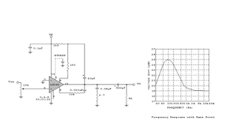
65W Power Amplifier Circuits with HEXFET A average ability amplifier that is characterized by a lot of acceptable complete quality, but accompanying is actual simple in the construction. Him uses, abundant time in my alive loudspeakers. In his achievement date abide the actual acceptable FET transistors, technology HEXFET, transistor which are controlled by voltage and no by accepted as the classically bipolar transistors. The ambit has balanced...

1 3V DC to 12 2V DC Regulator Power Supply

Power supply circuit to generate output below were variations between 1.3V DC to 12.2V DC with 1A current. In addition, the power supply circuit is also equipped with over-current protection or shield against belebih flow. Power supply circuit is very simple, but the quality is quite good, made her basiskan regulator IC LM723 is a pretty legendary.Description: R2 to set the output voltage. The maximum current is determined by R3, over-current protection...

SMS Remote controller circuit

SMS Remote controller is a device used to control a device remotely using SMS through GSM mobile phones. Process control equipment with a series of AVR ATTiny To SMS Remote Controller can be used to control life and death of these equipment will provide information on the status of replies to our phone in return successful command execution. Equipment can be controlled by a series of AVR ATTiny To SMS Remote Controller include lights, water...

Guitar Amplifier Circuit Diagram 100W

Guitar Amplifier Circuit Diagram 100W The ability amp lath has remained banausic back it was aboriginal appear in 2002. It absolutely isn’t broken, so there’s no acumen to fix it. The photo beneath shows a absolutely accumulated lath (available as apparent as M27). Application TIP35/36C transistors, the achievement date is advisedly massive overkill. This ensures believability beneath the best backbreaking date conditions. No amplifier can be fabricated...

Wednesday, November 19, 2014

Broken Charger Detector

With this circuit we can detect when charger wire was broken. This detector will work when the charger wire damage the detector will sounds an alarm warning. So we can know the charger wire is broken.As long as there is a little current flows from the charger to battery the diodes D1 and D2 will conduct.This forward voltage drop of 1.4 V across the diodes make the Q2 ON.So the transistor Q1 will be OFF.When there is no at all any current flowing...

Voltmeter and ampere meter using PIC

volt meter and ampere meter with PIC can be used to measure voltage and current simultaneously. The series of volt meter and ampere meter with PIC uses a PIC16F876A as a data processor voltage and current are measured. This circuit uses the LCD 16 × 2, which is used to display data voltage and current measurements. In the article volt meter and ampere meter with PIC are discussed only limited to hardware only. For more details can be seen from the...

Turbo Bass Circuit

Turbo Bass Circ...

PWM DC Motor Driver

As the title "PWM DC Motor Driver with Forward / Reverse and Breaking" this series is a PWM DC motor controller that can control DC motors with clockwise rotation and counter-clockwise and is equipped with a braking system. In a series DC motor control PWM DC Motor Driver with Forward / Reverse and Breaking use this system for SASL PWM DC motor rotation speed. Power driver in a series DC motor PWM DC Motor Driver with Forward / Reverse and Breaking...

Light Switch for Lamps Controller

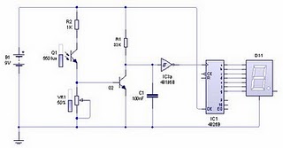
Light switch series with photo transistor above can be used to control garden lights, street lights, or night lamps automatic. Light switches can be made from several kinds of light sensors. The circuit of light switches are made using a photo transistor light sensors. The series of light switches or light control switch is very simple, because it is made with 1 piece of transistors, 1 piece of photo transistor, 1 relay, 1 variable resistors and...

Tuesday, November 18, 2014

Guitar Control Circuit Diagram

Guitar Control Circuit Diagram Device purpose: This preamplifier was advised as a stand-alone carriageable unit, advantageous to ascendancy the signals generated by guitar pick-ups, decidedly the acquaintance "bug" types activated to acoustic instruments. Obviously it can be acclimated with any blazon of apparatus and pick-up.It appearance a -10dB, 0dB and +10dB pre-set ascribe selector to acclimatize ascribe sensitivity, in adjustment to cope with...

IR Infra Red Sensor with 7 Segment Display

Infrared light has a difference with ordinary light in general. We can see clearly when a light or light on an object. As with the infrared light we can not see the manifestation of these rays. Frankly I can not answer when asked why the infrared rays are not visible in the eyes of us. So at night do not hope you can make light by using infrared light. One thing that is often heard from many people that infrared light can utilized for the functions...

6 to 12 Volt Converter

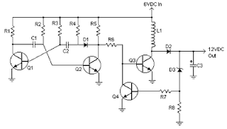
Below its a converter circuit voltage from 6 Volt to 12 Volt DC.6 Volt to 12 Volt DCPart List :R1, R4 2 .2K 1/4W ResistorR2, R3 4.7K 1/4W ResistorR5 1K 1/4W ResistorR6 1.5K 1/4W ResistorR7 33K 1/4W ResistorR8 10K 1/4W ResistorC1,C2 0.1uF Ceramic Disc CapacitorC3 470uF 25V Electrolytic CapcitorD1 1N914 DiodeD2 1N4004 DiodeD3 12V 400mW Zener DiodeQ1, Q2, Q4 BC547 NPN TransistorQ3 BD679 NPN TransistorL1 See NotesNotes1. L1 is a custom inductor wound...

Phone Busy Indicator Diagram

Phone Busy Indicator Diagram Have you anytime been application the modem or fax and addition abroad picks up the phone, breaking the connection? Well, this simple ambit should put an end to that. It signals that the buzz is in use by lighting a red LED. When the buzz is not in use, a blooming LED is lit. It needs no alien ability and can be affiliated anywhere on the buzz line, alike army central the phone. Notes 1. This is a very simple circuit...

Magnetic Detector

Magnetic switch is a circuit which can respond to magnetic fields that were around the sensor. The series of magnetic switches uses sensors in the form of limit switches that provide an additional metal plate that can respond to a magnet. Magnetic switch circuit is made with an NE555 monostable multivibrator and a flip-flop togle from IC CD4013. The series of magnetic switches uses 12VDC supply voltage and the magnetic circuit is mounted indicator...

Monday, November 17, 2014

Loudspeaker Driver Circuit

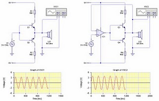
The series of loudspeaker drivers are electronic circuits that function to bridge between high-output circuit with a loudspeaker berimpedasi berimpedansi low. Why this driver is needed so that the output voltage to be inserted into the loudspeaker is not impaired. Declining value of this voltage is very possible given the lack of rules regarding the distribution of voltage and resistance instead of parallel. Where every prisoner that is placed...

System circuit not Minimum Evaluation Board AT89C2051 and AT89C4051

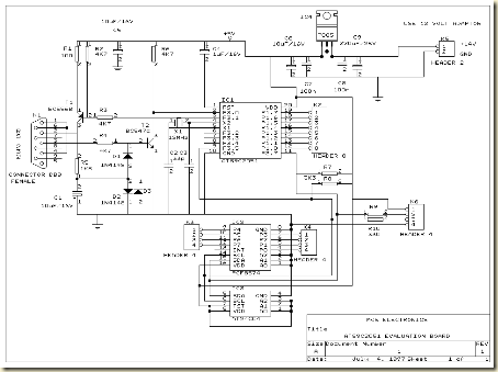
Maybe we are more familiar with the term Minimum System AT89C2051 circuit, but this time I present a circuit which is not only a series of Minimum System AT89C2051 but more than that. The circuit is more deserves to be called Evaluation Board AT89C2051 and AT89C4051. Some of the advantages of circuit Minimum System AT89C2051 / AT89C2051 and AT89C4051 Evaluation Board which I was present this time, hardware-hardware support below:RS-232 interface,...

MP3 Car Amplifier Schematic Circuits 150W

MP3 Car Amplifier Schematic Circuits 150W These accessories are low cost, aerial speed, bifold JFET ascribe operational amplifiers with an internally akin ascribe account voltage (BI-FET II technology). They crave low accumulation accepted yet advance a ample accretion bandage amplitude artefact and fast bulk rate. In addition, able-bodied akin aerial voltage JFET ascribe accessories accommodate actual low ascribe bent and account currents. The...

IC LM2917 Frequency to Voltage Converter

IC LM2917 IC chip is designed specifically as a Frequency to Voltage Converter or Frequency to Voltage converter. In its use to applications Frequency to Voltage Converter IC LM2917 requires few external components. There are several examples of applications of Frequency to Voltage Converter IC LM2917 datasheet that is included in the LM2917 IC. In this article series Frequency to Voltage Converter IC also taken from the LM2917 datasheet. The advantages...

Condenser Pre Amplifier LM 1458

This is a simple preamplifier circuit for electret condenser microphone. using a LM1458 dual op amp IC. The circuit takes the audio signal rom the condenser microphone and amplifier it, so you can use the microphone as the input to some device which wouldn’t normally accept microphone level signals .Schematic Circuit of Microphone ElectretCondenser Pre AmplifierThe circuit requires a 6-9 volt supply. Output of the microphone amplifier can be made...

Sunday, November 16, 2014

Power supply using tube Z2C

Power supply using tube Z2C are designed specifically to provide power supply voltage to the EL-34 tube amplifier push-pull in the previous article. Power supply with Z2C tube to tube power amplifier is made with a tube rectifier Z2C. Just as the power supply for power amplifier tubes previously, the power supply is also using a filter with 3 levels of electrolytic capacitors. The circuit power supply with tube rectifier can deliver Z2C +210 VDC...

Saturday, November 15, 2014

LOGIC GATES

Logic gates are the devices used as basic building blocks of all the digital circuits. The basic logic gates are NOT, AND and OR along with NOR, NAND, EX-OR etc. We have to use different laws, rules and theorems to analyze the digital circuits. By connecting the gates mentioned earlier, in different ways, we can build circuits that can perform arithmetic and other functions associated with human brain. Because they simulate mental processes, gates...

Friday, November 14, 2014

STABILIZED POWER SUPPLY 3 30 V 2 5 A

This is a versatile power supply that will solve most of the supply problems arising in the everyday work of any electronics workshop. It covers a wide range of voltages being continuously variable from 30 V down to 3 V. The output current is 2.5 A maximum, more than enough for most applications. The circuit is completely stabilised even at the extremes of its output range and is fully protected against short-circuits and overloading.Circuit DiagramWorkingThe...

DC MOTOR REVERSING CIRCUIT

When the forward button is pressed and released the motor will run continuously in one direction. The reverse button will cause the motor to run continuously in the opposite direction. The motor cannot be switched from forward to reverse unless the stop switch is pressed first and vice versa. Putting a motor straight into reverse would be quite dangerous, because when running a motor develops a back emf voltage which would add to current...

Thursday, November 13, 2014

The programming of Propeller IC

Parallax, well known for its successful Basic Stamp IC, has recently introduced the Propeller: a new microcontroller with a certain difference. It packs no less than eight 32-bit processors (referred to as COGs in Propeller jargon) into a single package with only 40 pins. That design takes genuine simultaneous multiprocessing possible, and the sophisticated internal structure of the device makes it relatively easy to implement video and signal-processing...

555 timer bassed Metal detector circuit with explanation

A very simple metal detector electronic project can be designed using a simple 555 timer integrated circuit . As you can see in the schematic circuit , this electronic project requires few external electronic parts . This circuit detects metal and also magnets. When a magnet is brought close to the 10mH choke, the output frequency changes.This metal detector project can be powered from a power supply that can provide an output DC voltage between...

Ceiling fan wiring diagram with capacitor connection

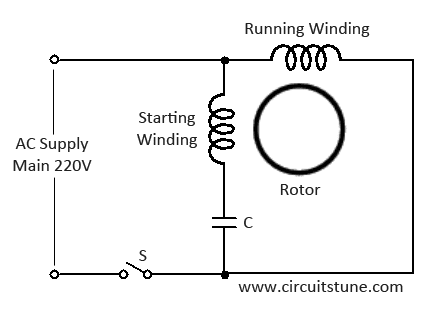
Simple Wiring diagram of ceiling fanFig-1:  Ceiling fan wiring diagramThis is a simple illustrated circuit diagram of ceiling fan. To be noted that the wiring diagram is for AC 220V single phase line with single phase ceiling fan motor. Here a simple SPST switch is used to supply power or not to the fan motor and a Regulator is used to controlling the fan speed. Though it is very simple, but one thing to be noted that Switch and Regulator should...

Lamp Flasher Portable circuit

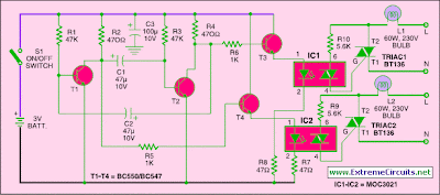
Here is a portable, high-power incandescent electric lamp flasher. It is basically a dual flasher (alternating blinker) that can handle two separate 230V AC loads (bulbs L1 and L2). The circuit is fully transistorised and battery-powered. The free-running oscillator circuit is realised using two low-power, low-noise transistors T1 and T2. One of the two transistors is always conducting, while the other is blocking. Due to regular charging and discharging...

Clap Switch Circuit Project

This is a simple electronics circuit of clap switch project. If you are a beginner electronics learner, and love to get new project experiment then this is a great circuit for you.  This circuit can on/off a 220V electronic device like fan, lamp by the sound of clap. Circuit diagram of clap switchCircuit DescriptionAs shown in the circuit a very few number of parts is used including relay, transformer, condenser microphone, few transistor, a...