Friday, October 31, 2014

Converting a DCM Motor Circuit Diagram

We recently bought a train set made by a renowned company and just couldn’t resist looking inside the locomotive. Although it did have an electronic decoder, the DCM motor was already available 35 (!) years ago. It is most likely that this motor is used due to financial constraints, because Märklin (as you probably guessed) also has a modern 5-pole motor as part of its range. Incidentally, they have recently introduced a brushless model. 

The DCM motor used in our locomotive is still an old-fashioned 3-pole series motor with an electromagnet to provide motive power. The new 5-pole motor has a permanent magnet. We therefore wondered if we couldn’t improve the driving characteristics if we powered the field winding separately, using a bridge rectifier and a 27 Ω current limiting resistor. This would effectively create a permanent magnet. The result was that the driving characteristics improved at lower speeds, but the initial acceleration remained the same. But a constant 0.5 A flows through the winding, which seems wasteful of the (limited) track power. A small circuit can reduce this current to less than half, making this technique more acceptable. 

Converting a DCM Motor Circuit diagram :


Converting
Converting a DCM Motor Circuit Diagram

The field winding has to be disconnected from the rest (3 wires). A freewheeling diode (D1, Schottky) is then connected across the whole winding. The centre tap of the winding is no longer used. When FET T1 turns on, the current through the winding increases from zero until it reaches about 0.5 A. At this current the voltage drop across R4-R7 becomes greater than the reference voltage across D2 and the opamp will turn off the FET. The current through the winding continues flowing via D1, gradually reducing in strength. When the current has fallen about 10% (due to hysteresis caused by R3), IC1 will turn on T1 again. The cur-rent will increase again to 0.5 A and the FET is turned off again. This goes on continuously.
.
The current through the field winding is fairly constant, creating a good imitation of a permanent magnet. The nice thing about this circuit is that the total current consumption is only about 0.2 A, whereas the current flow through the winding is a continuous 0.5 A. 

We made this modification because we wanted to convert the locomotive for use with a DCC decoder. A new controller is needed in any case, because the polarity on the rotor winding has to be reversed to change its direction of rotation. In the original motor this was done by using the other half of the winding.
There is also a good non-electrical alter-native: put a permanent magnet in the motor. But we didn’t have a suitable magnet, whereas all electronic parts could be picked straight from the spares box. 


Author : Karel Walraven

2 Siren Sound Use IC555

2 Siren Sound Use IC555
Function of the Two Siren Sound Circuit that is using IC 555. Siren Circuit is separated into three parts: low frequency production. The manufacturing shrill frequency and annex of production low frequency is obtained from IC1 connected to astable multi vibrator circuit frequency is prearranged by R1, C2 frequencies with the purpose of are advent revealed of pin 3 is almost 1 Hz through R2 to subsist noble 5. of IC2, a division manufacture high-frequency input next to Pin 5 pray tone the origin of oscillator IC2 is the move of voltage from the output of IC1 frequency of IC2 is being set by R3, C3, which, if C3 help. will be alive very low tone if C3 is a lesser amount of treble The output preference suffer to podium out at home three legs of IC2 to stimulate B of Q1 to amplify signals to drive speakers.

BENCH POWER SUPPLY

This power supply can be built in less than an hour on a piece of copper-laminate. The board acts as a heat-sink and the other components can be mounted as shown in the photo, by cutting strips to suit their placement.


The components are connected with enamelled wire and the transistor is bolted to the board to keep it cool.

The Bench Power Supply was designed to use old "C," "D" and lantern batteries, thats why there are no diodes or electrolytics. Collect all your old batteries and cells and connect them together to get at least 12v -14v.

The output of this power supply is regulated by a 10v zener made up of the characteristic zener voltage of 8.2v between the base-emitter leads of a BC547 transistor (in reverse bias) and approx 1.7v across a red LED. The circuit will deliver 0v - 9v at 500mA (depending on the life left in the cells your are using). The 10k pot adjusts the output voltage and the LED indicates the circuit is ON. Its a very good circuit to get the last of the energy from old cells.
 
source : http://www.talkingelectronics.com.au/projects/200TrCcts/200TrCcts.html

Thursday, October 30, 2014

Car Audio Amplifier Instalation Guide

Amplifier and speakers wiring. The amplifier does not always come with wire connection. You need a kit amp wiring harness sold separately. It is important to adjust the harness to the vehicle you have, to the right frequency and sound. The red wires (positive) is thicker than black (ground). A 12 -, 10 – or 8-gauge wire or lower is better sound quality.

Car

Connecting the power cable and head unit. Disconnect the negative battery cable car, then the positive. Connect the red amplifier (positive) to the positive battery cable. Strip one end of the thread about half an inch and squeeze the cable connector U-Connect the positive terminal of the battery and tighten. Slide the other end through the firewall of your car, which is located towards the rear under the hood. Drag the interior and on the back of the torso. You may need to unscrew the bottom plate on each side and pull the seat back to move the thread. Black lead to an O-ring and screws for the metal of the cars to squeeze into the trunk.

Check if your head unit has suspended two AV, the ends of the women. If not, you have to buy one and have it installed. AV wire supplied with the kit must be long enough to reach from the amplifier in the trunk of the radio. Connect the ends of the red and white male to the female ends of the amplifier and the radio. Then connect the son of the subwoofer amplifier. Connect the negative terminal of the battery.

Turn the key to your car and listen to the radio at low volume. Not at full power crank. You get a distorted sound, or a speaker can blow the air. You will feel the vibration in the car audio system.

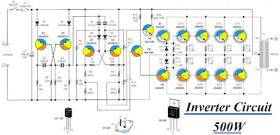
Inverter Circuit 12VDC to 220V 50Hz 500W

This is circuit Inverter 12VDC to 220V 50Hz 500W.
It easy to make and Low cost. Friends favorite circuit about the the inverter, because like working outdoors, or to backup storage to use when necessary. Most of this is circuit low power, which is not suitable for practical applications. My friends said that he would be about 500 Watt.

It is a good size. Use with television receivers and light bulbs as well. When looking for circuit. I get headaches. If you are a beginner or I can not buy expensive good quality circuits. Requires only one transistor. Or if you have free time. I want to build old circuit is alive again. This circuit will accommodate all your needs. It is a simple circuit. 

Inverter
Inverter 12VDC to 220V 50Hz 500W

The same principle, I take battery voltage 12V to produce a oscillator about 100 Hz and pass to a two frequency divider circuit is only 50HZ. And drive a 10 ampere transformer with 10 x 2N3055 transistor in parallel. By a single transistor has 2A, when I use 10 transistors or 5 pairs of drive high current output. The complexity of circuit, but the principle is not it, and it is the number of transistors on a basic, easy to buy. You may be modified 100 watt power inverter To the size of transistors and transformers as well

1500 W Cobra Power Inverter 12VDC to 120VAC

1500Power Inverter manufactured by Cobra, capable converting input battery 12VDC to become 120VAC with power loads (output) up to 1500W.

This inverter gives household power on the go. It converts battery power to 120 V AC household power, permitting you to power up office equipment and household appliances from your vehicle. This unit is ideal for such appliances as microwave ovens (1000 watts or much less), coffeemakers, laptops, TVs, video game consoles, CD and DVD players, cell phone chargers, and far more.

How The Cobra Power Inverter Works
The Cobra power inverter is an electronic item that has been created and built to take low-voltage DC (Direct Current) power from your automobile or other low-voltage power supplies and convert it to standard 115 volt AC (Alternating Current) power like the current youve inside your residence. This conversion process thereby allows you to make use of numerous of your household appliances and electronic goods in automobiles, RVs, boats, tractors, trucks, and practically anywhere else.

Cobra 1500 Watt Output Waveform
Some quite sensitive electronic equipment could not operate satisfactorily on "square wave" or "modified sine wave" power. The output waveform of the Cobra Inverter is actually a "square wave" or "modified sine wave." It truly is a stepped waveform created to have characteristics similar to the sine wave shape of utility power. A waveform of this nature is suitable for most AC loads, including linear and switching power suppliers used in electronic equipment, transformers, and motors.

AC receptacles
With three ground AC receptacles, you can connect and power multiple devices at as soon as.

USB Output
The 5-Volt USB output permits charging and operation of modern portable devices, for example iPods, BlackBerrys, and cell phones.

Remote On/Off Switch Capable
An optional Remote On/Off Switch could be connected to the Remote Jack, allowing you to turn the Cobra power inverter on or off from a convenient location when the inverter is installed out of reach.

Safety Features
The CPI 1575 will notify you with a flashing meter and alarm sound when there is a power issue, and will shut down for protection in the following situations:

  • Current Overload Protection--If the inverter is overloaded, itll shut down to protect itself.
  • Short Circuit Protection--If the AC output of the inverter is short-circuited for 1 second or more, it is going to shut down to safeguard itself.
  • Low Voltage Protection--If the input voltage drops to 10.0V or much less, the inverter will shut down to protect itself.
  • High Voltage Protection--If the DC input voltage rises above 15.0V, the inverter will shut down to safeguard itself.
  • Over Temperature Protection--If the internal temperature rises to 40 degrees C (104 degrees F), the inverter will shut down to safeguard itself. 

LM377 Power amplifier schematic

Different places and use also requires a different power amplifier as well. For this time i gave a circuit schematic power amplifier based on LM377 ic that has similarities with the LM378 and LM1877. Power is smoothly small ouput is 2 X 2.5 Watt and the impedance 4 ohms. Use of this amplifier suitable for portable radio tuner that can be taken every where.
Component description :

Resistor
R1___________________2K
R2___________________2K
R3___________________1M
R4___________________1M

Capacitor
C1___________________4.7uF 50V
C2___________________4.7uF 50V
C3___________________100n
C4___________________100n
C5___________________470uF 50V
C6___________________470uF 50V

IC
IC1__________________LM377 , LM378 , LM1877

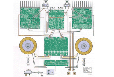
High End Power Amplifier Wiring Circuit

As the causes of the heat sink mounting surface to approximately 6 mm from the edge of the circle are fixed, assuming that the amplifier circuits mounted directly on the rails. This means that the leads of the transistors must be folded twice, so they are positioned properly, without a permanent mechanical stress in transistors. For high output transistors, the first corner a little closer to the plastic packaging than expected (in the wide part), otherwise the son of the rails or not to strike. Another possibility, which has the disadvantage that it weakens the structure, it is to grind enough metal in appropriate locations, to provide sufficient clearance. We have consciously rejected that option.

High-End

Once you have taken on these details and transistors can be easily placed on the free flat heatsink with her son through the holes in the circuit you can use the locations of the holes on the back mark of the radiators. Of course you must do so before the transistors are soldered to the track but is according to the holes for the final determination of the amplification circuits made in the base plate. Once the output transistors and their driver were mounted on the heat sink and soldered to the boards, the bottom plate can be removed easily.

Be careful not too much force on the terminals of the transistors, if the plates are exposed in this way.
Power transistors T14 and T15 must be mounted on heatsink bs with insulators (mica discs), while the other three transistors (Til, T12 and T13) can be screwed directly onto the heat sink. Make sure you use thermal paste to all the transistors.

After all the holes for the remaining circuits, transformers, switches and lights (front) and the ventilation slots in the chassis, you can screw up everything and you install the wiring.

Use well-designed audio cable connected to the input of the amplifier boards on the terminals in the vicinity of the inputs on the board overdrive display. With the two ground terminals to the input jacks for connecting the housing to the grounds of the two channels. This will avoid creating loops. The inputs to the outputs of the amplifier are in the middle of the board control overdrive removed. The best way to connect, to use thin, flexible cable, to connect the output jacks.

Wednesday, October 29, 2014

Remote Mains Switch Low Voltage Diagram Circuit

This circuit allows a 240V mains appliance to be controlled remotely via low-voltage cabling and a pushbutton switch. The mains appliance (in this case, a light bulb) is switched with a suitably-rated relay. All of the electronics is housed in an ABS box located in proximity to the appliance. The pushbutton switch and plugpack are located remotely and can be wired up with 3-core alarm cable or similar. Cable lengths of 20m or more are feasible with this arrangement. When the switch (S1) is pressed, the input (pin 8) of IC1c is briefly pulled low via the 10mF capacitor, which is initially discharged.

Circuit diagram:
Low-Voltage Remote Mains Switch Circuit Diagram

The output (pin 10) immediately goes high and this is inverted and fed back to the second input (pin 9) via another gate in the quad NAND package (IC1d). In conjunction with the 1MW resistor and 470nF capacitor, IC1d eliminates the effects of contact "bounce" by ensuring that IC1c’s output remains high for a predetermined period. The output from IC1c drives the clock input of a 4013 D-type flip-flop (IC2). The flipflop is wired for a "toggle" function by virtue of the Q-bar connection back to the D input. A 2.2MW resistor and 100nF capacitor improve circuit noise immunity. Each time the switch is pressed, the flipflop output (pin 13) toggles, switching the transistor (Q1) and relay on or off. Note that all mains wiring must be properly installed and completely insulated so that there is no possibility of it contacting the low-voltage side of the circuit.
Author: Bob Hammond - Copyright: Silicon Chip Elecronics

MP3 Player Booster Circuits

MP3 players are all the rage these days. The smaller ones in memory-stick format are particularly easy to take with you; your very own ‘personal sound system’ on the move! It’s when you want others to share your taste in music that you find these players to have a lack of power. You can get round this problem with the help of the MP3 booster, a small amplifier that can be used to connect your MP3 player directly to your Hi-Fi. When you next invite your friends to a party you can ask them to bring their ‘personal music’ as well as the usual drinks!

But first we have to build this booster! The small battery-powered players have an output signal that is more than sufficient to drive a set of 32 Ohm headphones. You’ll often find that with an output of 1mW the sound pressure level (SPL) produced can reach up to 90 dB. This would be sufficient to cause permanent damage to your hearing after only one hour! The maximum output voltage will then be around 200mV. This, however, is insufficient to fully drive a power amplifier. For this you’ll need an extra circuit that boosts the output voltage.

Power amps usually require 1 V for maximum output, hence the signal has to be amplified by a factor of five. We will also have to bear in mind that quieter recordings may need to be amplified even more. We’ve used a simple method here to select the gain, which avoids the use of potentiometers. After all, the MP3 player already has its own volume control. We decided to have two gain settings on the booster, one of three times and the other ten times. Amplifiers IC1A and IC1B (for the right and left channels) are housed in a single package, a TS922IN.

The output signal of the MP3 player is fed via a stereo cable and socket K1 to the inputs of the amplifiers. The gain depends on the relationship between resistors R2 and R1 (R6 and R5 for the other channel) and is equal to ten times. When you add jumper JP1 (JP2), resistor R3 (R7) will be connected in parallel with the negative feedback resistor R1 (R6), which causes the gain to be reduced to about three. When you start using the booster you can decide which gain setting works best for you.

Circuit diagram:


MP3 Booster Circuit Diagram

Resistor R4 (R8) takes the amplified MP3 signal to the output socket K2 (K3). A cable then connects these phono sockets to the input of your power amplifier. The resistors connected in series with the output (R4 and R8) are there to keep the booster stable when a long cable is connected to its output. Cables have an unwelcome, parasitic capacitance. This capacitive effect could (due to phase shifts of the signal) affect the negative feedback of the booster in such a way that a positive feed back occurs, with the result that the booster oscillates and possibly damages the power amplifier!

The resistors (R4 and R8) effectively isolate the output of the booster from the parasitic capacitance of the output cable. They also protect the booster outputs from short circuits. We’ve used a TS922IN opamp in this booster because it can operate at very low supply voltages (the maximum is only 12 V!), but can still output a reasonable current (80 mA max.). For the supply we’ve used rechargeable batteries (e.g. NiCd or NiMH cells) so that we don’t need a mains supply.

To keep the number of cells required as small as possible, we’ve chosen a supply voltage of 5 volt; this can be supplied by four rechargeable batteries. It is also possible to use four ordinary, non-rechargeable batteries; it’s true that the supply voltage then becomes a bit higher (6 Volts), but that won’t cause any harm. Since we’ve used a symmetrical supply for the booster (2 x 2 batteries), it will be easiest if you use two separate battery holders, each with two AA cells. The two holders are connected in series.

Make sure that the batteries are connected the right way round; the positive of one always has to be connected to the negative of the next. This also applies to the connection between the two battery holders. S1A/B is a double pole switch, which is used to turn both halves of the battery supply on or off simultaneously. If you can’t find the (dual) opamp we’ve used (or an equivalent), you could always use standard opamps such as the NE5532, TL082 or TL072. These do need a higher supply voltage to operate properly. In these cases you should use two 9 V batteries and replace resistor R9 with a 15 kΩ one.

Do take care when you connect the circuit to your power amplifier because the output signal can be a lot larger and you could overload the power amplifier. (Although you’re more likely to damage the loudspeakers, rather than the amplifier!) (Please note that these two 9 V batteries can’t be used as a supply for the TS922IN!) In our circuit we’ve used a stereo jack socket for the input and phono sockets for the output because these are the most compatible with MP3 players and power amplifiers respectively. If you wanted to, you could solder shielded cables directly to the circuit instead, with the correct plugs on the ends. You’ll never find yourself without the correct connection leads in that case!
Source: Elektor Electronics 12-2006

Transformerless 5 Volt DC Power Supply

An increasing number of appliances draw a very small current from the power supply. If you need to design a mains-powered device, you could generally choose between a linear and a switch-mode power supply. However, what if the appliance’s total power consumption is very small? Transformer-based power supplies are bulky, while the switchers are generally made to provide greater current output, with a significant increase in complexity, problems involving PCB layout and, inherently, reduced reliability.

Is it possible to create a simple, minimum part-count mains (230 VAC primary) power supply, without transformers or coils, capable of delivering about 100mA at, say, 5 V? A general approach could be to employ a highly inefficient stabilizer that would rectify AC and, utilizing a zener diode to provide a 5.1 V output, dissipate all the excess from 5.1 V to (230×√2) volts in a resistor. Even if the load would require only about 10mA, the loss would be approximately 3 watts, so a significant heat dissipation would occur even for such a small power consumption.


 At 100mA, the useless dissipation would go over 30 W, making this scheme completely unacceptable. Power conversion efficiency is not a major consideration here; instead, the basic problem is how to reduce heavy dissipation and protect the components from burning out. The circuit shown here is one of the simplest ways to achieve the above goals in practice. A JVR varistor is used for over-voltage/surge protection. Voltage divider R1-R2 follows the rectified 230 V and, when it is high enough, T1 turns on and T3 cannot conduct.

When the rectified voltage drops, T1 turns off and T3 starts to conduct current into the reservoir capacitor C1. The interception point (the moment when T1 turns off) is set by P1 (usually set to about 3k3), which controls the total output current capacity of the power supply: reducing P1 makes T1 react later, stopping T3 later, so more current is supplied, but with increased heat dissipation. Components T2, R3 and C2 form a typical ‘soft start’ circuit to reduce current spikes — this is necessary in order to limit C1’s charging current when the power supply is initially turned on. At a given setting of P1, the output current through R5 is constant.

Thus, load R4 takes as much current as it requires, while the rest goes through a zener diode, D5. Knowing the maximum current drawn by the load allows adjusting P1 to such a value as to provide a total current through R5 just 5 to 6mA over the maximum required by the load. In this way, unnecessary dissipation is much reduced, with zener stabilization function preserved. Zener diode D5 also protects C1 from over voltages, thus enabling te use of low-cost 16 V electrolytics. The current flow through R5 and D5, even when the load is disconnected, prevents T3’s gate-source voltage from rising too much and causing damage to device. In addition, T1 need not be a high-voltage transistor, but its current gain should exceed 120 (e.g. BC546B, or even BC547C can be used).

Mouse keyboard Switch Unit Diagram Circuit

Unplugging or re-connecting equipment to the serial COM or PS2 connector always gives problems if the PC is running. Even if you only need to swap a mouse or changeover from a graphics keyboard to a standard keyboard. The chances are that the connected equipment will not communicate with the PC, it will always be necessary to re-boot. If you are really unlucky you may have damaged the PC or the peripheral device. In order to switch equipment successfully it is necessary to follow a sequence. The clock and data lines need to be disconnected from the device before the power line is removed. And likewise the power line must be connected first to the new device before the clock and data lines are re-connected.

This sequence is also used by the USB connector but achieved rather more simply by using different length pins in the connector. The circuit shown here in Figure 1 performs the switching sequence electronically. The clock and data lines from the PC are connected via the N.C. contacts of relay RE2 through the bistable relay RE1 to connector K3. Pressing push-button S1 will activate relay RE2 thereby disconnecting the data and clock lines also while S1 is held down the semiconductor switch IC1B will be opened, allowing the voltage on C4 to charge up through R4. After approximately 0.2 s the voltage level on C4 will be high enough to switch on IC1A, this in turn will switch on T1 energizing one of the coils of the bistable relay RE1 and routing the clock, data and power to connector K2.


When S1 is released relay RE2 will switch the data and clock lines through to the PC via connector K1. It should be noted that the push-button must be pressed for about 0.5s otherwise the circuit will not operate correctly. Switching back over to connector K3 is achieved similarly by pressing S2. The current required to switch the relays is relatively large for the serial interface to cope with so the energy necessary is stored in two relatively large capacitors (C2 and C3) and these are charged through resistors R1 and R6 respectively. The disadvantage is that the circuit needs approximately 0.5 minute between switch-overs to ensure these capacitors have sufficient charge.

The current consumption of the entire circuit however is reduced to just a few milliamps. The PCB is designed to accept PS2 style connectors but if you are using an older PC that needs 9 pin sub D connectors then these will need to be connected to the PCB via flying leads. In this case the mouse driver software configures pin 9 as the clock, pin 1 as the data, pin 8 (CTS) as the voltage supply pin and pin 5 as earth.

Resistors:
R1 = 2kΩ2
R2 = 47kΩ
R3 = 10kΩ
R4 = 4kΩ7
R5 = 1kΩ
R6 = 1kΩ2
Capacitors:
C1 = 10µF 10V radial
C2 = 1000µF 10V radial
C3 = 2200µF 10V radial
C4 = 2µF2 10V radial
Semiconductors:
D1-D5 = 1N4148
T1 = BC547
IC1 = 4066 or 74HCT4066
Miscellaneous:
RE1 = bistable relay 4 c/o contacts
RE2 = monostable relay 2 c/o contacts
K1,K2,K3 = 6-way Mini-DIN socket (pins at 240°, PCB mount
S1,S2 = push-button (ITTD6-R)

Petrol Gas Switch For A Pajero Diagram Circuit

My current vehicle, a Pajero, was modified for dual fuel - ie, petrol and gas. However, its necessary to run the vehicle on petrol at regular intervals to stop the injectors from clogging up. This simple circuit allows the vehicle to be started using petrol and then automatically switches it to gas when the speed exceeds 45km/h and the brake pedal is pressed. Alternatively, the vehicle may be run on petrol simply by switching the existing petrol/gas switch to petrol. You can also start the vehicle on gas by pressing the brake pedal while starting the vehicle. The circuit is based on an LM324 dual op amp, with both op amps wired as comparators. It works like this: IC1a buffers the signal from the vehicles speed sensor and drives an output filter network (D1, a 560kO resistor and a 10µF capacitor) to produce a DC voltage thats proportional to the vehicles speed.

Circuit diagram:

This voltage is then applied to pin 5 of IC1b and compared with the voltage set by trimpot VR1. When pin 7 of IC1b goes high, transistor Q1 turns on. This also turns on transistor Q2 when the brake pedal is pressed (pressing the brake pedal applies +12V from the brake light circuit to Q2s emitter). And when Q2 turns on, relay 1 turns on and its contacts switch to the gas position. Trimpot VR1 must be adjusted so that IC1bs pin 7 output switches high when the desired trigger speed is reached (ie, 45km/h). In effect, the speed signal is ANDed with the brake light signal to turn on the relay. The vehicle has been running this circuit for several years now and is still running well, with no further injector cleans required.
Author: J. Malnar - Copyright: Silicon Chip Electronics

Tuesday, October 28, 2014

About Microcontroller


The microcontroller is a special type of microprocessor and it integrates the components of microprocessor taking part in single break off which builds a single integrated circuit, it contains the central processing unit basic, input/output peripheral and these microcontrollers needs the policy to hoard the data from inputs. The microcontroller can come about broadly classified like three types as 8-trace, 16-bit, and 32-bit microcontroller.

The 8-bit microcontroller consists of home buses and ALU. The ALU is an calculation and logic group. It performs arithmetic operations like addition, subtraction and commonsense operations like AND, before gate operations. The microcontroller by and large contains several digit of all-purpose perseverance input/output pins. for this reason, what time General purpose I/O Pins are referred to an input state, they used to read the sensors and as soon as it is configured to output stage. The pins can drive strategy seeing that LEDs. The architectures of microcontroller give round about designs include wide-ranging idea computer with further come to RAM, ROM otherwise I/O functions.

Interrupts: 
Interrupt used here the microcontroller is used to wake up the device from a low power have a lie-down mode and these interrupt sources are device dependent.

About

Brainwashing: 
Normally, many micro-controllers were involuntary single in gathering language, but at the present time various important-level indoctrination languages can furthermore come about used instead of programming of microcontroller. thus, the programs of microcontroller ought to be fit in the sphere of the open on marker code recollection and the memory may possibly be read-simply memory before instant read only recall. In microcontroller to convert high-level and assembler language codes into organization language, assemblers and compilers are used.

Facial appearance: 
1. Typically microcontroller includes a CPU, ROM, RAM, and timers. 
2. A microcontroller is autonomous and self-limited. 
3. It is designed in lieu of a express task to control the regard classification. 
4. It is typically designed using CMOS.

Applications of Microcontroller: 
1. Blood cell recorder cum analyzer, ECG present cum recorder and unwearied monitoring system. 
2. nearly of transmission systems like cell phone phones, cable tube, and FAX machinery. 
3. Peripheral plans of a mainframe like LAN Controller, DRAM Controller, laser imprinter Controller. 
4. It is in addition used fashionable automotive applications like contravention procedure, and a dynamic drive control 
5. CRT put on view controller, a spectrum analyzer, frequency analyzer and so on.

For this reason the microcontroller contains its own chronometer, twin ports, peripheral functions and especially it contains the own recall. trendy the PIC microcontroller, it contains both the RAM reminiscence to storeroom no more than the data and gleam memory somewhere the orders are stored. Additionally, it too contains unusual kinds of orders solid and series contact functions.

Mono Power Amplifier A1015 BD140 TIP2955

Typically audio amplifier stereo amplifier to a two amplifier. And if a mono amplifier is a single speaker. However this circuit command be present extended to the mono two loudspeaker.But not a equivalence or else serialization access.This makes it needless impedance of the speaker has altered.But will remain to utilize the spokeswoman as a replacement for of the resistance - Collection Peter (RC) of the transistor.The circuit can be alive prolonged to 2 loudspeaker itself.

Mono Power Amplifier - A1015, BD140 ,TIP2955 Circuit Diagram
What time raising the power supply circuit and the audio to input. the audio sign coupling to through the C1 and R1 to increase with the Q1.Which Q1 serves like the Regional Pre amp amplifier to power up to a one point.already conveyance it to Q2.Which Q2 is connected to emitter follower circuit.be active as a driver amplifier intimate section from the pre amp section provides added power to drive the Q3 perform. and Q3 motivation provide while a Regional Power amp amplifier output to the spokeswoman.The opinion of the audio intimate through the VR1 and R2 to enter the pin B of Q2.To control the stability of working instead of well brought-up.This circuit is an output of 40 milliwatts watts of distortion of the gesture rate is by the side of 0.1 percent.And frequency response from 15 Hz - 200 kHz.

Isobaric loading Subwoofer Box

Isobaric is not in reality an inclusion type but a woofer loading method. Isobaric loading can be there used fashionable conjunction with several of the area types, not including perhaps never-ending baffle. Isobaric loading consists of two woofers coupled at once by a suddenly field which is simply slow a sufficient amount to prevent the two woofers from striking solitary an added. The woofers possibly will take place mounted look to face, back to back otherwise front to back. However it is essential to exhibit the woofers firing within time with lone any more.

Isobaric

In order to accomplish this with the woofers firing front to front or else back to back individual of the woofers orator leads be obliged to be real reversed with respect to the other woofer. Isobaric loading is regularly used whilst place is on a premium before a top figure amount of woofers desire to be used featuring in a particular volume of space. By isobarically loading the woofers, a box of barely partly the size of a individual woofer box is desirable. pro pattern, if a 12″ woofer requires a two cubic end box, the same 12″ woofer isobarically loaded lone requires a lone cubic bottom box. The cost of this design, other than doubling the woofer cost, is a reduction featuring in the subwoofer usage efficiency by three decibels (if both woofers are prearranged the same power at the same time as a single woofer), which is equivalent to halving the amplifier power. extra, minor box subwoofer designs enclose all but eliminated the need in support of isobaric loading in car audio and it has fallen vetoed of popularity.

Advantages of this design are increased linearity voguish the orator movement, let fall legroom supplies, and increased power conduct. Disadvantages are increased cost, increased design and compilation complexity, and decreased efficiency.

5 1 Classic Home Theater System Energy

Low Distortion and Resonance - spokesman method is distortion- otherwise resonance-without charge, but Energy has achieved a significantly decrease distortion level, a plainly audible perfection.


Classic

The Take Classic 5.1 home theater system also offers terrific performance and great features:

  • Our patented Convergent Source Module (CSM) 3-edge your way poly-titanium woofer and .75-inch hyperbolic aluminum-field tweeter -the kindness of Energy speakers
  • Patented corrugated Elliptical Surround woofers create from top to toe efficiency, low distortion
  • An aluminum auditorium tweeter on behalf of sonic accuracy
  • Front and rear venting for additional powerful low response
Take Classic raises the piece for 5.1 narrator classification performance. It includes a powerful 200-watt subwoofer with a front-firing seaport, 8-shuffle driver and wavy Elliptical Surround™ in support of deep with the intention of you feel when much as hear. The Convergent Source Module (CSM), with its 3-shuffle poly-titanium woofer and .75-inch hyperbolic aluminum-pitch tweeter, focuses sound for clearer dialogue and stirring melody. The CSM gives soundtracks a dynamic frequency range and a colossal soundstage, used for smooth, realistic sound from every one satellite lecturer and the base channel. song and motion picture lovers rejoice. Take Classic puts the passion back into your favorite films.
Exclusive Energy® Brand Technologies

Convergent Source Module
The Convergent Source Module, before CSM, provides broad dispersion, low distortion and amazing midrange performance. The lecturers midrange and tweeter are positioned inside close proximity to individual an alternative and accomplish seeing that a single source, by this means increasing overall dispersion and falling some lobing effect. The chambering of the middle and tweeter lowers the drivers resonance, plummeting distortion.

wavy Elliptical Surround knowledge
Energys patented ridged Elliptical Surround technology (U.S. patent #6,725,967, Canadian patent #2,407,123) increases excursion, eliminates distortion and raises efficiency on woofers and subwoofers. The Elliptical Surround encompasses the conduit, allowing it to move identically concerning both instructions, follow-on in come up to nil distortion. And while standard designs are often plagued with surround dimpling, which causes them to give off in and off of segment and distort on all listening levels, Energys designs arent influenced by dimpling on all, as a substitute proprietary grooved Elliptical Surround expertise allows representing a better conduit come up, resultant trendy greater efficiency. This design as well lets the conduit do greater crest to peak movement, in this way allowing it to travel added than bend in half the distance of the competition. These attributes enable Energy woofers and subwoofers to move incredible amounts of air, ultimately allowing them to joke about drop frequencies with greater low lean-to and fidelity.

come again?s voguish the Box
A 6-example, soaring spin black place of Energy Take Classic 5.1 speakers: 4-Take satellite speakers, 1-faultlessly matched Take interior channel spokeswoman, 1-perfectly matched Take powered subwoofer; 1-owners guide.

Technical Specifications
  • Frequency Response - Sat: 115Hz-20KHz; Center: 110Hz-20KHz; Subwoofer: 33Hz-150Hz +/- 3dB
  • Crossover purpose - 2.9 kHz
  • Sensitivity - 89dB
  • Power use - Sat & core: 100 Watts; Subwoofer: 200 Watts
  • Recommended Amplifier Power - 20 - 100 Watts RMS (permanent)
  • Impedance - 8-ohm compatible
  • Subwoofer adaptable Low Pass Filter - 40Hz-150Hz @ 18dB/octave
  • Tweeter - ¾-shuffle (19 mm) Hyperbolic™ aluminum-ground
  • Woofer - Sat & crux: 3-edge your way poly-titanium; junior: 8" IM cone-shaped tool with Patented grooved Elliptical Surround
  • Dimensions (inches) - Sat: 6 7/8 x 4 1/8 x 4 1/8; Center: 4 1/8 x 10 1/4 x 4 1/8; Subwoofer: 12 5/8 x 12 5/8 x 12 5/8 (add 2 1/6" pro feet)
  • power - Sat: 2.9 lbs; foundation: 3.2 lbs; Subwoofer: 19.7 lbs

Performance Tips: 
The center channel spokeswoman needs to be alive centrally located so so as to the dialogue appears to be approach from the center of the screen. It needs to be more than or else underneath the overseer, while faithfully to it as feasible. If youon the subject of using a rear projection television, the nearly all likely option is to place it over the screen. If you say a front projection method, you have choices-rack mounting, otherwise placement on furniture, in support of illustration. It is principal, though, to place the orator so to facilitate its front frame is even with the edge of the shelf or else stand underneath it. unsolicited diffraction occurs whilst the foundation channel is too far back into a cabinet or else other exterior with edges with the aim of possibly will impede sound dispersion.

In support of not here or else utterly front channels, the distance concerning the speakers be supposed to live 6-8 feet on smallest amount for the greatest stereo imaging. The optimum extent identity is rectangular, with the speakers along solitary of the shorter walls, facing the opposite margin. If probable, figure out not place speakers hostile to a fence or else by rear of a bookshelf; corner placement is generally the most evil option. Try to keep the speakers-especially rear vented models-next to smallest amount two feet from the plane behind it, save you manipulation a vent plug. pro superlative results mounting on a rear cage up, pose the speakers so they flank the major listening area and item with regard to the front of the opportunity. They be supposed to be situated raised to a height of approximately six feet and ought to ideally give a window of six feet involving them.

The three a good number normal subwoofer locations include corners (which can upshot taking part in boomy otherwise exaggerated low frequency response), placement along a mountain, away from the corner (producing moderate low performance with increased fidelity terminated corner placement), otherwise beside a front spokeswoman (creating a better blend with the front speaker, but sacrificing overall volume). Experimentation with subwoofer placement is highly encouraged; slight adjustments can create giant differences clothed in sound reproduction. To test subwoofer placement, install it in the short term in your chief listening attitude and march around the listening space while on stage a familiar bit of melody until you catch the most excellent sounding position.

Monday, October 27, 2014

Mini Guitar Bass Amplifier Diagram Circuit

Output power: 6W into 4 Ohm load, FET input stage - Passive Tone Control
Tiny, portable Guitar Amplifiers are useful for practice on the go and in bedroom/living room environment. Usually, they can be battery powered and feature a headphone output. This project is formed by an FET input circuitry, featuring a High/Low sensitivity switch, followed by a passive Tone Control circuit suitable to Guitar or Bass. After the Volume control, a 6W IC power amplifier follows, powered by a 12-14V dc external supply Adaptor or from batteries, and driving a 4 Ohm 10 or 13cm (4"/5") diameter car loudspeaker. Private listening by means of headphones is also possible.

Circuit diagram:Mini
Mini Guitar-Bass Amplifier Circuit Diagram
Parts:

P1______________1M Linear Potentiometer
P2____________100K Log Potentiometer
R1_____________68K 1/4W Resistor
R2____________470K 1/4W Resistor
R3______________2K7 1/4W Resistor
R4______________8K2 1/4W Resistor
R5____________680R 1/4W Resistor
R6____________220K 1/4W Resistor
R7_____________39R 1/4W Resistor
R8______________2R2 1/4W Resistor
R9____________220R 1/4W Resistor
R10_____________1R 1/4W Resistor
R11___________100R 1/2W Resistor
R12_____________1K5 1/4W Resistor
C1____________100pF 63V Polystyrene or Ceramic Capacitor
C2,C5,C9,C14__100nF 63V Polyester Capacitors
C3____________100µF 25V Electrolytic Capacitor
C4_____________47µF 25V Electrolytic Capacitor
C6______________4n7 63V Polyester Capacitor
C7____________470pF 63V Polystyrene or Ceramic Capacitor
C8______________2µ2 25V Electrolytic Capacitor
C10___________470µF 25V Electrolytic Capacitor
C11____________22nF 63V Polyester Capacitor
C12__________2200µF 25V Electrolytic Capacitor
C13__________1000µF 25V Electrolytic Capacitor
D1______________3mm red LED
Q1____________BF245 or 2N3819 General-purpose N-Channel FET
IC1_________TDA2003 10W Car Radio Audio Amplifier IC
SW1,SW2________SPST toggle or slide Switches
J1____________6.3mm Mono Jack socket
J2____________6.3mm Stereo Jack socket (switched)
J3_____________Mini DC Power Socket
SPKR__________4 Ohm Car Loudspeaker 100 or 130mm diameter

Notes:
  • Connect the output Plug of a 12 - 14V dc 500mA Power Supply Adaptor to J3
  • Please note that if the voltage supply will exceed 18V dc the IC will shut down automatically
Technical data:

Output power (1KHz sinewave):
6W RMS into 4 Ohm at 14.4V supply
Sensitivity:
50mV RMS input for full output
Frequency response:
25Hz to 20kHz -3dB with the cursor of P1 in center position
Total harmonic distortion:
0.05 - 4.5W RMS: 0.15% 6W RMS: 10%

Tone Control Frequency Response:

2 x 22W BTL Car Audio Amplifier DA1553CQ

This is a 22 Watt car stereo audio amplifier. The circuit is based by a single IC TDA1553 with a few peripheral components, this IC hope against hope code name your stereo car audio classification. The IC TDA1553CQ contains 2×22 W amplifiers with differential input stages and can exist used in favor of connection applications.. The expansion of apiece amplifier is fixed by the side of 26 dB. The device is primarily residential for car broadcasting applications.

Circuit Diagram 2 x 22W-BTL Car Audio Amplifier Using DA1553CQ

Circuit Diagram 2 x 22W-BTL Car Audio Amplifier Using TDA1553CQ 
  • The TDA1553CQ IC have got to be present fitted with adequately sized cook sinks.
  • unite a 10K POT happening string with the input because volume control if you need. Not publicized in circuit diagram.
  • employment 12V DC in favor of powering the circuit.


What time a diminutive-circuit to ground occurs, which forces a DC voltage across the loudspeaker of >= vs., a built-in protection circuit becomes full of life and limits the DC voltage across the loudspeaker to <= vs.. pin 12 detects the status of the protection circuit (e.g. meant for diagnostic purposes).

If slightly output is unfriendly-circuited to ground in the course of the side with mode, it becomes hopeless to switch the circuit to the mute otherwise operating condition. happening this event the supply current determination remain some degree of to a little milliamps.

Fuse Failure Alarm 2 LED

This circuit motivation let somebody see the performance of the equipment,otherwise Check the fuse arrived the circuit.The circuit is insignificant and the power supply voltage of all kinds. It parade with LED, 2-color in single. Which is cathode normal kind,the anode has two separate terminals. If the circuit is functioning accurately LED, it exposed in environmentally friendly colour.


The display is red, at what time the fuse voguish the circuit is damaged.The resistor R1 limits the current to stream through the LED is going on for 2 mA.This is a sufficient amount to do the LED light.If it lowers the R1 down, the LED light up. In the regular action of the circuit and The fuse is not damaged. The zener diode to prevent the green and red LED light up at once.Zener diode prevents the LED is sea green and red illumination at the same time. The high-pitched efficiency LED, whilst connected in the sphere of congruence. The red LED uses high-pressure, so with the intention of single green LED illumination up only. Diodes D3 and D4 command prevent perilous in support of the LED. While the semi cycle denial voltage of the alternating current voltage.However, if the DC supply voltage.I perform not include to application diode protection.

Video Distribution Amplifier

With the amount of equipment during in entertainment centers at present the need to survive able to vary the profit of the audio otherwise capture on film sign is required. I found this instance circuit ready to lend a hand while used in conjunction with the Universal Descrambler and a Stabilizer circuit I built instead of making copies of cassette tapes. It not just allowable me the capacity to fine melody the video strength it and helped me redouble the recorded audio which typically becomes poor as making tape copies. Circuit act is straight redirect designed for amplifier circuits. The minute channel for the audio amplifier is made up of the same components excluding the other partly of IC1 is used. Pin 6 & 5 are inputs and 7 is the output.
Video Distribution Amplifier

Sunday, October 26, 2014

LM2876 40W audio power amplifier Diagram Circuit

Using the LM2876 high-performance audio power amplifier circuit can be designed a very simple high efficiency power audio amplifier electronic project capable of delivering 40W of continuous average power to an 8Ω load with 0.1% THD+N from 20Hz–20kHz.
The performance of the LM2876 high-performance audio power amplifier, utilizing its Self Peak Instantaneous Temperature (°Ke) (SPiKe™) protection circuitry, puts it in a class above discrete and hybrid amplifiers by providing an inherently, dynamically protected Safe Operating Area (SOA). SPiKe protection means that these parts are completely safeguarded at the output against overvoltage, undervoltage, overloads, including shorts to the supplies, thermal runaway, and instantaneous temperature peaks.
The LM2876 maintains an excellent signal-to-noise ratio of greater than 95dB (min) with a typical low noise floor of 2.0μV.

As you can see in the circuit diagram , this 40W high-performance audio power amplifier electronic project require few external electronic parts and require few knowledge .
The muting function of the LM2876 allows the user to mute the music going into the amplifier by drawing less than 0.5 mA out of pin 8 of the device.
Upon system power-up the under-voltage protection circuitry allows the power supplies and their corresponding caps to come up close to their full values before turning on the LM2876 such that no DC output spikes occur.
The LM2876 contains overvoltage protection circuitry that limits the output current to approximately 4Apeak while also providing voltage clamping, though not through internal clamping diodes.
The LM2876 has a sophisticated thermal protection scheme to prevent long-term thermal stress to the device. When the temperature on the die reaches 165°C, the LM2876 shuts down. It starts operating again when the die temperature drops to about 155°C
The LM2876 high-performance audio power amplifier circuit operates over a wide input voltage range , from 20 up to 70 volts , but typically a dual 30 volt power supply ( or a single 60 volt in this case ) will be work fine

Multi channel audio systems

Multi-channel audio systems are widely used within novel sound campaign. The word “multi-channel audio” process with the intention of, the audio method can transpire accomplished of conduct multiple audio channels (more often than not called audio tracks) to rebuild the sound on a multi-loudspeaker setup.
Usually two digits separated by a decimal (.) end (2.1, 4.1, 5.1, 6.1, 7.1, and the rest.) are used to classify the various kinds of orator fix-up, this total basically depending on how many audio tracks are used. about audio systems solitary suffer a single channel (called monophonic sound otherwise single channel audio) or two channels (stereophonic sound or else 2.0 channel sound)
The initial numeral shows the quantity of primary channels (called satellite units), both of which are reproduced on a single presenter (these speakers are accomplished in place of use the frequency range from 100Hz to 22Khz), while the back up (decimal figure) refers to the presence of LFE (Low Frequency Effect), which is reproduced on a subwoofer.

Diagram 2N3904 small Metronome


This is knock the melody. It uses begin flasher circuit in building sound click keen go up at a loudspeaker. But each time at Q2 (2N3906) work by origin frequency circuit that use RC and Q1(2N3904) ,R2 – 50K use fine work rate repeatedly through 20-280 sections time per minute.

By value change of C1 (22uF) will change the tone of voice in the sound click at happens.
eleccircuit.com/small-metronome-using-2n3904/

Saturday, October 25, 2014

Supply Voltage Monitor Diagram Circuit

A circuit for monitoring supply voltages of ±5 V and ±12 V is readily constructed as shown in the diagram. It is appreciably simpler than the usual monitors that use comparators, and AND gates. The circuit is not intended to indicate the level of the inputs. In normal operation, transistors T1 and T3 must be seen as current sources. The drop across resistors R1 and R2 is 6.3 V (12 –5 –0.7). This means that the current is 6.3mA and this flows through diode D1 when all four voltages are present. However, if for instance, the –5 V line fails, transistor T3 remains on but the base-emitter junction of T2 is no longer biased, so that this transistor is cut off. When this happens, there is no current through D which then goes out.

Supply

How to build Power Flip Flop Using A Triac

Modern electronics is indispensable for every large model railroad system, and it provides a solution to almost every problem. Although ready-made products are exorbitantly expensive, clever electronics hobbyists try to use a minimum number of components to achieve optimum results together with low costs. This approach can be demonstrated using the rather unusual semiconductor power flip-flop described here. A flip-flop is a toggling circuit with two stable switching states (bistable multivibrator). It maintains its output state even in the absence of an input pulse.

Flip-flops can easily be implemented using triacs if no DC voltage is available. Triacs are also so inexpensive that they are often used by model railway builders as semiconductor power switches. The decisive advantage of triacs is that they are bi-directional, which means they can be triggered during both the positive and the negative half-cycle by applying an AC voltage to the gate electrode (G). The polarity of the trigger voltage is thus irrelevant. Triggering with a DC current is also possible. Figure 1 shows the circuit diagram of such a power flop-flop. A permanent magnet is fitted to the model train, and when it travels from left to right, the magnet switches the flip-flop on and off via reed switches S1 and S2.

Circuit diagram:

In order for this to work in both directions of travel, another pair of reed switches (S3 and S4) is connected in parallel with S1 and S2. Briefly closing S1 or S3 triggers the triac. The RC network C1/R2, which acts as a phase shifter, maintains the trigger current. The current through R2, C1 and the gate electrode (G) reaches its maximum value when the voltage across the load passes through zero. This causes the triac to be triggered anew for each half-cycle, even though no pulse is present at the gate. It remains triggered until S2 or S4 is closed, which causes it to return to the blocking state.The load can be incandescent lamps in the station area (platform lighting) or a

solenoid-operated device, such as a crossing gate. The LED connected across the output (with a rectifier diode) indicates the state of the flip-flop. The circuit shown here is designed for use in a model railway system, but there is no reason why it could not be used for other applications. The reed switches can also be replaced by normal pushbutton switches. For the commonly used TIC206D triac, which has a maximum current rating of 4 A, no heat sink is necessary in this application unless a load current exceeding 1 A must be supplied continuously or for an extended period of time. If the switch-on or switch-off pulse proves to be inadequate, the value of electrolytic capacitor C1 must be increased slightly.
Author: R. Edlinger - Copyright: Elektor July-August 2004

How to build Personal alarm

Small, portable, anti-bag-snatching unit Also suitable for doors and windows control

Circuit diagram


Parts:

  • R1 330K 1/4W Resistor
  • R2 100R 1/4W Resistor
  • C1 10nF 63V Polyester or Ceramic Capacitor
  • C2 100µF 25V Electrolytic Capacitor
  • Q1 BC547 45V 100mA NPN Transistor
  • Q2 BC327 45V 800mA PNP Transistor
  • SW1 Reed Switch and small magnet (See Notes)
  • SPKR 8 Ohm Loudspeaker (See Notes)
  • B1 3V Battery (two A or AA cells wired in series etc.)

Device purpose:

This circuit, enclosed in a small plastic box, can be placed into a bag or handbag. A small magnet is placed close to the reed switch and connected to the hand or the clothes of the person carrying the bag by means of a tiny cord. If the bag is snatched abruptly, the magnet looses its contact with the reed switch, SW1 opens, the circuit starts oscillating and the loudspeaker emits a loud alarm sound. The device can be reverse connected, i.e. the box can be placed in a pocket and the cord connected to the bag. This device can be very useful in signalling the opening of a door or window: place the box on the frame and the magnet on the movable part in a way that magnet and reed switch are very close when the door or window is closed.

Circuit operation:

A complementary transistor-pair is wired as a high efficiency oscillator, directly driving a small loudspeaker. Low part-count and 3V battery supply enable a very compact construction.

Notes:

  • The loudspeaker can be any type, its dimensions are limited only by the box that will contain it.
  • An on-off switch is unnecessary because the stand-by current drawing is less than 20µA.
  • Current consumption when the alarm is sounding is about 100mA.
  • If the circuit is used as anti-bag-snatching, SW1 can be replaced by a 3.5mm mono Jack socket and the magnet by a 3.5mm. mono Jack plug with its internal leads shorted. The Jack plug will be connected with the tiny cord etc.
  • Do not supply this circuit with voltages exceeding 4.5V: it will not work and Q2 could be damaged. In any case a 3V supply is the best compromise.

Simple Automatic Switch For Audio Power Amplifier


Simple Automatic Switch For Audio Power Amplifier Circuit of an automatic switch for audio power amplifier stage is presented here. The circuit uses stereo preamplifier output to detect the presence of audio to switch the audio power amplifier on only when audio is present. The circuit thus helps curtail power wastage. IC1 is used as an inverting adder. The input signals from left and right channels are combined to form a common signal for IC2, which is used as an open loop comparator. IC3 (NE556) is a dual timer. Its second section, i.e., IC3(b), is configured as monostable multivibrator. Output of IC3(b) is used to switch the power amplifier on or off through a Darlington pair formed by transistors T1 and T2. IC3(a) is used to trigger the monostable multivibrator whenever an input signal is sensed.

Circuit diagram:
Automatic Switch For Audio Power Amplifier-Circuit-Diagram
Automatic Switch For Audio Power Amplifier Circuit Diagram

Under ‘no signal’ condition, pin 3 of IC2 is negative with respect to its pin 2. Hence the output of IC2 is low and as a result output of IC3(a) is high. Since there is no trigger at pin 8 of IC3(b), the output of IC3(b) will be low and the amplifier will be off. When an input singal is applied to IC1, IC2 converts the inverted sum of the input signals into a rectangular waveform by comparing it with a constant voltage which can be controlled by varying potentiometer VR1. When the output of IC2 is high, output pin 5 of IC3 goes low, thus triggering the monostable multivibrator. As soon as the audio input to IC1 stops, pin 5 of IC3 goes high and pin 1 of IC3 discharges through capacitor C3, thus resetting the monostable multivibrator. 

Hence, as long as input signals are applied, the amplifier remains ‘on.’ When the input signals are removed, i.e., when signal level is zero, the amplifier switches off after the mono flip-flop delay period determined by the values of resistor R8 and capacitor C3. If no input signals are sensed within this time, the amplifier turns off—else it remains on. Power supply for the circuit can be obtained from the power supply of the amplifier. Hence, the circuit can be permanently fitted in the amplifier box itself. The main switch of the amplifier should be always kept on. Resistors R1 and R2 are used to divide single voltage supply into two equal parts.

Capacitors C1 and C2 are used as regulators and also as an AC bypass for input signals. Diode D1 is used so that loading fluctuations in power amplifier do not affect circuit regulation. Transisitor T2 acts as a high voltage switch which may be replaced by any other high voltage switching transistor satisfying amplifier current requirements. Value of resistor R10 should be modified for large current requirement. The LED glows when the amplifier is on. The circuit is very useful and relieves one from putting the amplifier on and off every time one plays a cassette or radio etc. 

Source : EFY

5 Zone Alarm System

This is a complete alarm system with 5 independent zones suitable for a small office or home environment. It uses just 3 CMOS ICs and features a timed entry / exit zone, 4 immediate zones and a panic button. There are indicators for each zone a "system armed" indicator. The schematic is as follows:


5 zone alarm


Circuit Notes
Each zone uses a normally closed contact. These can be micro switches or standard alarm contacts (usually reed switches). Suitable switches can be bought from alarm shops and concealed in door frames, or window ledges.

Zone 1 is a timed zone which must be used as the entry and exit point of the building. Zones 2 - 5 are immediate zones, which will trigger the alarm with no delay. Some RF immunity is provided for long wiring runs by the input capacitors, C1-C5. C7 and R14 also form a transient suppressor. The key switch acts as the Set/Unset and Reset switch. For good security this should be the metal type with a key.

Operation
At switch on, C6 will charge via R11, this acts as the exit delay and is set to around 30 seconds. This can be altered by varying either C6 or R11. Once the timing period has elapsed, LED6 will light, meaning the system is armed. LED6 may be mounted externally (at the bell box for example) and provides visual indication that the system has set. Once set any contact that opens will trigger the alarm, including Zone 1. To prevent triggering the alarm on entry to the building, the concealed re-entry switch must be operated. This will discharge C6 and start the entry timer. The re-entry switch could be a concealed reed switch, located anywhere in a door frame, but invisible to the eye. The panic switch, when pressed, will trigger the alarm when set. Relay contacts RLA1 provide the latch, RLA2 operate the siren or buzzer.


Author : Andy Collinson

Using 555 Timer Voltage Controlled Switch


In this circuit the 555 timer is used in a novel way, as a voltage controlled switch.The old and omnipresent NE555 can be very good at something it was not meant for: driving relays or other loads up to 200 mA. The picture shows an example circuit: if the input level rises over 2/3 of the supply voltage - it will turn on the relay, and the relay will stay on until the level at the input drops below one third of the supply voltage.

If the relay and D1 were connected between pin 3 and ground, the relay would be activated when the input voltage drops below one third, and deactivated when the input voltage goes over two thirds of the supply voltage. It is also a nice advantage that the input requires only about 1 uA, which is something bipolar transistors cant compete with. (This high impedance input must not be left open.) A large hysteresis makes the circuit immune to noise. The output (pin 3) can only be either high or low (voltage-wise), and it changes its state almost instantenously, regardless of the input signal shape.


The voltage drop across the NE555s output stage (at 35-100 mA) is 0.3-2.0 V, depending on the way the relay is connected and the exact current it draws. D1 is absolutely vital to the safety of the integrated circuit.

Simple Circuit Board Checker

This little circuit indicates the basic integrity of a printed board, detecting 0V, positive supply voltage from less than 3V to 30V and floating parts. If the probe is floating, as it would be in a broken track, then both LEDs barely light up, since there is no current to drive the transistors, but if the probe touches 0V or a positive voltage one or other lights. A digital signal should light them in proportion to the mark-space ratio whereas the output of a circuit oscillating at a frequency rate below about 20Hz will cause the LEDs to flicker alternatively. The LEDs will illuminate always at a constant intensity, no matter the voltage supply used, because they are fed by a very simple FET constant-current generator (Q1).

Circuit diagram:


Circuit Board Checker Circuit Diagram

 
Parts:

R1 = 22K
R2 = 22K
D1 = Red LED
D2 = Green LED
Q1 = BF245
Q2 = BC547
Q3 = BC557

Notes:
  • The Black clip must be connected to the negative ground of the board under test.
  • The Red clip should be connected to a positive voltage source (not exceeding 30V) available on the same board.
  • Metal probe is suitable for this circuit.
  • Two Miniature Crocodile Clips (Red and Black) are also necessary.

Solid State Relay Required Only 50uA Drive Current

This circuit demands a control current that is 100 times smaller than that needed by a typical optically isolated solid state relays. It is ideal for battery-powered systems. Using a combination of a high current TRIAC and a very sensitive low current SCR, the circuit can control about 600 watts of power to load while providing full isolation and transient protection.

Sourced by :link

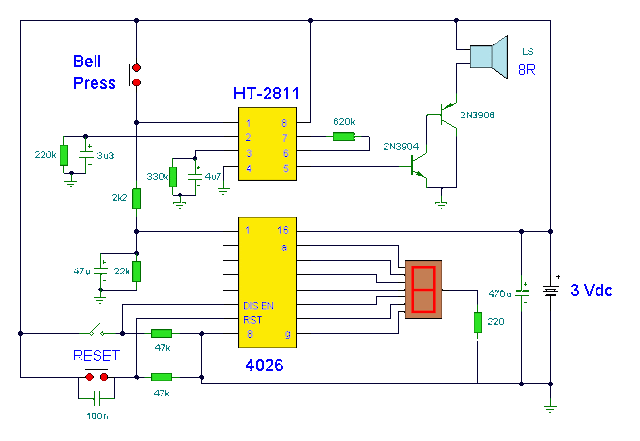
Electronic Doorbell with Counter Circuit Diagram

This circuit is a doorbell with counter, that means it counts how many times the bell is triggered. It uses a chip synthesizer sound, the HT-2811 ms nothing prevents you from using another device sound generator. The HT-2811 reproduces the sound of a "ding-dong" doorbell. Besides this ic, the circuit includes a CMOS 4026 and Display Driver IC which counts the total number of visitors.

 Electronic Doorbell with Counter Circuit Diagram


Electronic Doorbell with Counter Circuit Diagram

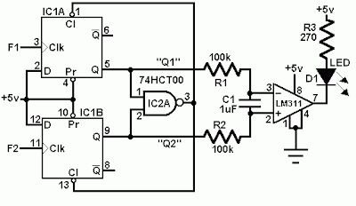
Simple Comperator Frequency LED Circuit Diagram

This Simple Comparator Frequency LED Circuit Diagram uses a comparison frequency IC 74HCT00, the device enabling frequency pulses are compared. Frequency F1 (signal frequency channel 1) and F2 (signal frequency channel 2). If the two frequencies are equal, then LED lights.


Comperator Frequency LED Circuit Diagram

Simple Comperator Frequency LED Circuit Diagram


Build a Smart battery charger

This is a smart battery charger can protect your vehicles battery from failing and will prolong its life – theyre fully automatic so you can connect and forget.


Build a Smart battery charger

This is a smart battery charger can protect your vehicles battery from failing and will prolong its life – theyre fully automatic so you can connect and forget.


Build a Blocking Circuit with Alarm for Bicycle

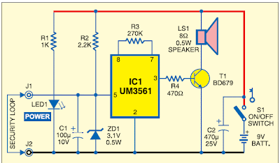
Here is an interesting circuit, it is used to make a kind of lock or locks for bicycles, it allows owners to implement a bicycle lock and electronic alarm with a low cost. The operation of the electronic lock is simple, it has a circuit that uses a tone generator IC UM3561, this IC generates a sound when your bike has the protection wire that surrounds the wheel broken.

 Blocking Circuit with Alarm for Bicycle Circuit Diagram

Blocking Circuit with Alarm for Bicycle


Click here to download complete project